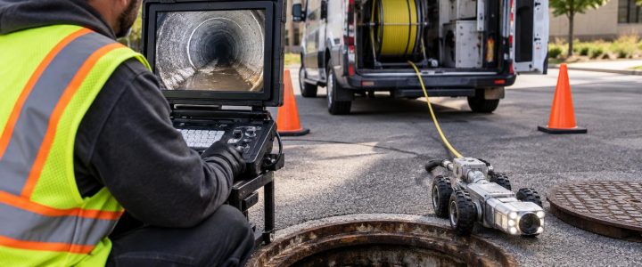
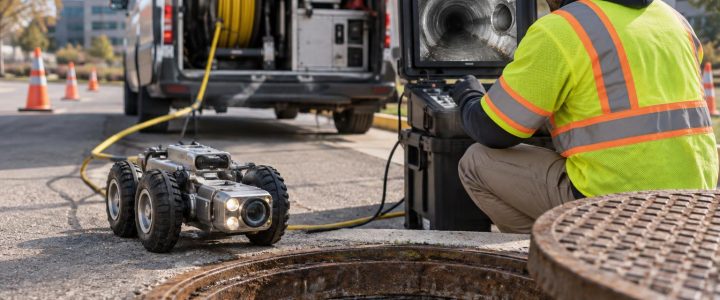
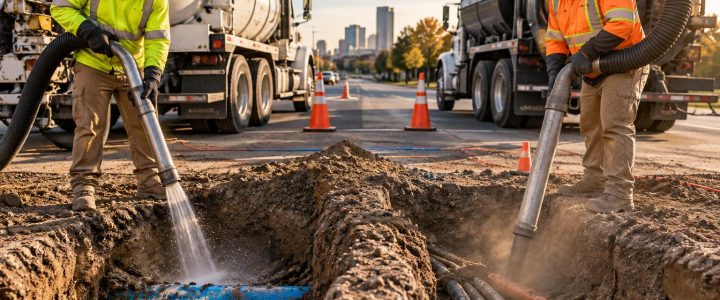
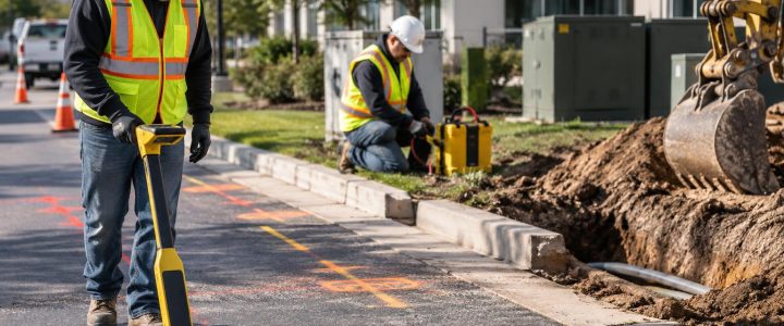
Utility locating is an important first step, but it does not always answer the questions that drive design and construction decisions. A locate mark, an electromagnetic signal, or a Ground Penetrating Radar interpretation may indicate where a utility is likely to be. When a proposed excavation, bore path, structure, or drainage line depends on the utility’s actual position, physical exposure may be necessary.
Utility test holes, also called potholes or daylighting holes, use vacuum excavation to carefully remove soil around a known or suspected utility. Once the facility is exposed, the project team can observe and document characteristics that cannot be confirmed reliably from a geophysical signal alone. That information can help engineers adjust a design, help contractors plan a safe excavation sequence, and help owners resolve conflicts before work reaches a critical path.
The point is not to dig holes everywhere. Effective utility potholing services are part of a focused investigation: expose the utilities and conflict points that have the greatest effect on cost, constructability, safety, and schedule.
Utility locating and utility verification are not the same
Utility locating and utility verification serve different purposes. Both are valuable, and neither replaces the other.
- Utility locating uses records research, visible features, electromagnetic methods, GPR, and other techniques to identify and designate utilities or subsurface features. This work can establish a useful interpreted path and may provide an estimated depth under favorable conditions.
- Utility verification physically exposes a specific utility or feature. The exposed portion can then be measured, observed, photographed, and documented for the project’s needs.
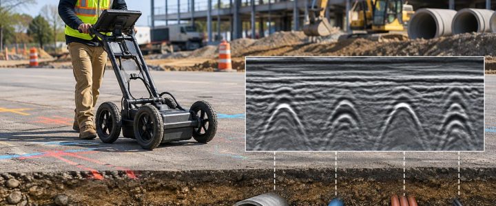
Electromagnetic locating works best when a utility is conductive or has a usable tracer wire and can be connected to or induced with a signal. GPR can help identify changes in subsurface conditions, but its results depend on soil, moisture, material, congestion, and operator interpretation. Neither method alone can always establish the precise depth, outside diameter, material, or configuration required at a planned crossing.
Vacuum excavation for utilities is often the next step when the consequences of being wrong are high. It provides direct observation of the utility at a selected point rather than relying only on records or an interpreted signal.
What a utility test hole can physically verify
A properly planned test hole can produce practical field information for design and construction. The exact information available depends on the portion exposed, access, soil conditions, safety requirements, and whether the utility can be fully uncovered around its circumference.
Actual horizontal position at the test-hole location
After exposure, the utility’s position can be measured relative to a project baseline, a curb, a building corner, survey control, or other established reference. This is useful when a marked route does not align with plans or when several parallel utilities are difficult to distinguish from the surface.
A single pothole confirms position only at that location. It should not be assumed that a utility follows a perfectly straight line between holes. Changes in direction, offsets, abandoned connections, repairs, and undocumented reroutes can occur.
Measured depth and surveyed elevation
These terms should be kept separate:
- Estimated depth is an interpreted depth produced by a locating method. It can be useful for planning, but it is not physical confirmation.
- Measured depth after exposure is the vertical distance from a defined surface reference to the utility at the test hole.
- Surveyed elevation is the utility elevation tied to a project datum through appropriate survey procedures.
A vacuum excavation crew can expose the utility needed for measurement, but vacuum excavation does not automatically create a surveyed elevation. When a design profile, gravity drainage connection, clearance requirement, or utility crossing requires precise coordinates, the exposed point should be captured by a qualified survey process using the project’s required control and datum.
Utility size, material, and configuration
Physical utility exposure can reveal observable characteristics such as:
- Pipe outside diameter or conduit diameter
- Pipe or conduit material, where visible and identifiable
- Number and arrangement of conduits in a duct bank
- Casing pipes, encasement, insulation, or protective coverings
- Bundles of communication conduits or cables
- Pipe joints, fittings, valves, offsets, or branch connections
- Whether the exposed feature appears active, abandoned, or damaged, subject to confirmation by the responsible utility or owner
These observations matter because utility records may list only a general size or utility type. A marked line also cannot reliably show whether a communication route contains one conduit or several, whether a pipe is inside a casing, or whether a crossing includes fittings that affect available clearance.
Exposure does not establish utility ownership or operating status by itself. It also represents conditions at the exposed area, not necessarily every point along the route. Teams should coordinate with the facility owner when confirmation, protection requirements, or shutdown decisions are needed.
How test-hole information supports SUE and Quality Level A work
Subsurface Utility Engineering, or SUE, is a structured approach to investigating and documenting existing utilities for engineering and construction purposes. In the ASCE 38-22 framework, Quality Level B generally refers to geophysical designation of utility routes, while Quality Level A involves the highest level of accuracy through physical exposure and measurement at specific points.
Both the ASCE 38-22 standard and the Federal Highway Administration’s SUE guidance describe physical exposure as the method used to obtain the most reliable point-specific utility information. Quality Level A is not simply a hole in the ground. The investigation, measurements, documentation, horizontal and vertical position, and project requirements all matter.
Not every vacuum excavation project is a complete SUE investigation, and not every test hole automatically satisfies all Quality Level A requirements. However, a well-planned utility test hole can provide the physical field evidence needed to support QL-A utility locating when it is performed and documented to the applicable scope.
For projects requiring a coordinated investigation, Visionary Subsurface Solutions can combine test-hole work with Subsurface Utility Engineering and QL-B services to help teams move from designated utility routes to targeted physical verification.
When engineers and contractors should specify utility potholing
Utility daylighting is most valuable when a decision depends on a known condition rather than a reasonable estimate. Consider utility test hole services when any of the following apply:
- A proposed utility, foundation, retaining wall, or drainage system may conflict with an existing line.
- Two utilities appear to cross and the vertical separation is unknown.
- A proposed horizontal directional drilling path passes near existing infrastructure.
- Plans, record drawings, and field locate results do not agree.
- A facility’s material, diameter, duct-bank arrangement, or casing needs confirmation.
- A contractor needs to expose a known utility before mechanical excavation begins nearby.
- A roadway, streetscape, or redevelopment project has dense and poorly documented utilities.
- An engineer needs a reliable elevation for a profile adjustment or utility relocation decision.
For example, an EM locate may designate a signal path across a proposed storm line. Before changing grades or moving a structure, a test hole can expose the existing facility, document its depth and apparent size, and allow the team to determine whether a conflict exists at that location. If design-grade information is needed, the exposed utility can then be surveyed.
Plan test holes around decisions, not just marks
Random potholing can create useful observations, but it may not answer the questions that matter most. A better approach starts with the proposed work and identifies the locations where verified information changes a decision.
A practical planning sequence
- Review the proposed work. Identify excavations, bores, structures, utility crossings, and grade-sensitive areas.
- Compile available information. Compare utility records, design drawings, site observations, and prior locating results.
- Identify uncertainty with consequences. Focus on crossings, congested corridors, connection points, and areas where a depth error would affect the design or work method.
- Select test-hole locations and required observations. Define whether the purpose is horizontal position, depth, elevation, size, material, clearance, or configuration.
- Plan access and controls. Address traffic, surface type, equipment staging, access limitations, restoration, spoil handling, and required permits or owner coordination.
- Document the exposure. Record measurements, reference points, photographs, observations, and any limitations. Obtain survey data when the project requires coordinates or elevations.
- Communicate the result. Give designers and field crews clear information about what was confirmed, where it was confirmed, and what remains uncertain.
This process helps avoid a common mistake: treating every exposed utility as fully understood. Test-hole data is location-specific. Good documentation states the utility observed, the point of exposure, the measurement method, the reference or datum used, and any conditions that limited observation.
Hydro excavation or air excavation?
Both hydro excavation and air excavation are non-destructive excavation methods that pair a cutting medium with a powerful vacuum system. They are selected based on project conditions, not a one-size-fits-all rule.
Hydro excavation uses controlled water to loosen soil for vacuum removal. It can be productive in many soil types, including compacted material, but produces slurry that requires containment, hauling, and disposal consistent with site and local requirements. Water use and freezing weather may also affect planning.
Air excavation uses compressed air to loosen soil for removal. It may be useful where minimizing water is important or where slurry disposal is a concern. However, soil response varies considerably, and dry spoil, dust control, and excavation production can be important considerations.
Neither method is risk-free, and neither is universally better. Soil type, groundwater, depth, congestion, utility sensitivity, surface restoration, access, weather, disposal requirements, and the project’s documentation needs should guide the method selection.
Vacuum excavation reduces risk, but it still requires careful work
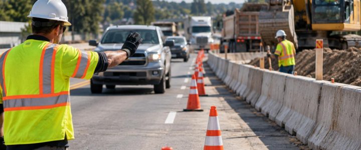
Compared with conventional mechanical excavation immediately around known or suspected utilities, vacuum excavation can reduce the chance of a damaging bucket strike by removing soil in a more controlled manner. It remains active excavation work, however. The work area still needs appropriate planning, trained personnel, equipment controls, utility-owner requirements, traffic management where needed, and safe excavation practices.
Congested utility corridors, deep targets, wet soils, frozen ground, limited equipment access, and unstable excavation conditions can all affect the work. Some facilities may require special exposure procedures or direct coordination with the owner. The goal is controlled verification, not a guarantee that every underground feature will be found or that no damage can occur.
Frequently asked questions about utility test holes
Can a test hole confirm utility depth?
Yes, a test hole can allow depth to be measured from a defined surface reference after the utility is physically exposed. If the project requires an elevation tied to a design datum, surveying or another appropriate measurement procedure is needed.
Can a test hole confirm a utility’s size and material?
It can document size, material, and configuration that are visible at the exposed point. The extent of the exposure and access around the facility affect what can be observed. Findings should be documented as point-specific observations.
How many utility test holes does a project need?
There is no fixed number. The right number depends on the proposed work, utility density, consequences of a conflict, available records, and the locations where verification will affect the design or construction plan.
Should utility potholing happen before construction?
For high-risk crossings, unknown depths, planned bores, and designs that depend on utility clearance, early verification can give the project team time to adjust before crews and equipment are committed. Test holes can also be valuable during construction when field conditions differ from the plans.
Get field evidence before assumptions become conflicts
When utility information will affect a design profile, excavation plan, bore path, or construction sequence, physical verification can be a practical next step after locating. Visionary Subsurface Solutions provides vacuum excavation and QL-A utility exposure services for projects throughout Pennsylvania, New Jersey, Delaware, Maryland, New York, and the Washington, D.C. to New York City corridor. Contact our team to discuss the utility questions, test-hole locations, and documentation needs for your project.