A utility test hole is more than an opening in the ground. Its value comes from the information collected after a utility has been physically exposed. Without complete notes, measurements, photos, and survey coordination where needed, a daylighted utility may still leave the design team and field crews guessing.
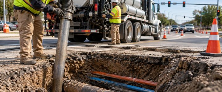
Vacuum excavation gives investigators a way to expose underground infrastructure with less reliance on conventional mechanical digging near known or suspected utilities. Once the utility is visible, the team can observe and document details that may not be reliably determined from utility records, electromagnetic locating, or Ground Penetrating Radar (GPR) alone.
For engineers, surveyors, contractors, and SUE professionals, a consistent test-hole record helps turn utility daylighting into usable information for profiles, conflict reviews, bid planning, bore-path decisions, and excavation planning.
Start with the distinction: locating is not physical verification
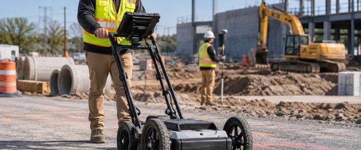
Utility locating and utility verification serve different purposes. Electromagnetic (EM) locating can trace certain conductive lines and estimate a utility position. GPR can identify subsurface anomalies and may help interpret possible utility routes or other buried features. Both methods are important parts of a planned investigation, but their results remain interpretations affected by access, congestion, signal distortion, soil conditions, and other site factors.
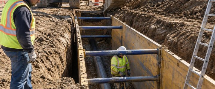
A vacuum-excavated test hole physically exposes the utility. That exposure can allow the team to observe its actual horizontal position at the hole, measured depth, outside diameter or configuration, material, and relationship to nearby infrastructure.
In the Subsurface Utility Engineering process, Quality Level B generally involves geophysical designation of utilities, while Quality Level A involves the highest level of accuracy through physical exposure and measurement. The Federal Highway Administration’s SUE guidance and ASCE standards resources describe physical verification as a key part of obtaining Quality Level A information. A test hole does not automatically qualify an investigation as QL-A, however. The work must be planned, performed, measured, and documented in a manner appropriate to the project and its stated requirements.
The core information to capture at every utility test hole
The exact deliverable should be established before fieldwork begins. Still, most utility potholing and utility daylighting services benefit from a standard set of field records.
1. Test-hole identification and location
Give every test hole a unique identifier that matches the plans, field sketch, survey file, and photographs. Record the street address or project limits, nearby station and offset if applicable, and clear reference points.
When design requires coordinate-quality horizontal information, have the exposed utility location surveyed or measured using an agreed project control method. A paint mark, GPS point from a phone, or approximate offset is not a substitute for a survey when precise coordinates are needed for design.
- Test-hole number
- Date and time of exposure
- Project name and location reference
- Station, offset, grid coordinate, or other project control reference
- Utility operator or owner, if independently confirmed through records or identification—not assumed from appearance alone
2. Utility type and observable characteristics
Record what is actually visible. This may include a water main, gas line, electric duct bank, communications conduit, sanitary sewer, storm pipe, abandoned line, casing, or an unknown facility. Avoid filling gaps with assumptions. If the use or ownership of a facility cannot be confirmed, label it accordingly and identify the basis for any preliminary interpretation.
Physical utility exposure may allow documentation of:
- Pipe or conduit material, such as steel, ductile iron, PVC, HDPE, concrete, clay, or another observable material
- Outside diameter or approximate size, including the method used to measure it
- Number of conduits in a bank
- Duct-bank width and visible configuration
- Casing pipe presence and apparent size
- Visible warning tape, tracer wire, concrete encasement, or protective covering
- Apparent condition, such as coating loss, corrosion, cracking, deformation, or prior repair, when visible and within the limits of the exposure
A single exposure does not confirm that these characteristics remain the same along the entire route. For example, a conduit bank can change configuration, a main can transition in material, and a pipe can enter a casing between test-hole locations.
3. Depth, elevation, and measurement method
Depth is often discussed loosely, but a useful record explains exactly what was measured and from where. Note the surface reference, such as top of curb, existing grade, pavement surface, or a temporary benchmark. Then identify the point on the utility that was measured: top of pipe, top of conduit, centerline, invert, or bottom of duct bank.
These terms should not be treated as interchangeable:
- Estimated depth: A depth estimate produced by a geophysical locating method. It may be useful for planning, but it is not the same as a physical measurement.
- Measured depth: A field measurement taken after the utility has been exposed, tied to a stated surface reference.
- Surveyed elevation: An elevation obtained by survey or another project-approved method and referenced to the project vertical datum.
Vacuum excavation can expose a utility for measurement, but it does not automatically create a surveyed elevation. If a civil design profile, gravity system connection, or utility crossing decision depends on vertical accuracy, coordinate the test hole with the survey team and document the datum, shot location, and feature measured.
4. Utility crossings and vertical separation
Where two facilities appear to conflict, expose enough of the crossing to establish the actual relationship. Record which utility passes over or under the other, the measured separation, and the measurement points used. A note such as “water crosses gas” may be insufficient for construction coordination.
A crossing record should identify:
- Both facilities and their test-hole identifiers
- Top, centerline, invert, or bottom elevations measured for each facility
- Vertical separation and how it was calculated
- Horizontal relationship at the exposed point
- Whether the crossing was fully exposed or partly inferred from the available opening
- Any visible encasement, casing, or protective material affecting the interpretation
For congested sites, more than one exposure may be needed. A utility can curve, change elevation, or transition into a different configuration before reaching the proposed work area.
5. Photographs and field sketches
Clear photographs provide useful context when paired with measurements. Take overview photos that show the hole and surrounding reference points, then close-up photos showing the facility, scale, material, conduits, and crossing conditions. A labeled measuring rod or tape can help communicate size and depth, provided it does not obstruct the utility or create a safety issue.
A simple field sketch can capture information photographs may miss, including the direction of each utility, the surface reference used for measurement, offsets to fixed features, and the relationship between several exposed facilities. Label the sketch with the test-hole number and orientation.
Match the test-hole record to the project decision
Not every utility exposure needs the same level of detail. The right scope depends on what the project team needs to decide.
For civil design and utility coordination
Design teams commonly need surveyed horizontal and vertical data, utility size, material, configuration, and crossing information. Test-hole locations should focus on proposed structures, deep utilities, utility crossings, tie-in points, low points, and areas where a proposed grade or profile leaves limited clearance.
For excavation and construction planning
Contractors may need confirmed utility depth and alignment near a trench, foundation, wall, pole base, or pavement removal area. The record should clearly identify the limits of physical exposure. A utility exposed ten feet away from the planned cut does not necessarily establish its exact position at the cut.
For horizontal directional drilling
Directional drilling teams may need daylighted crossings, entry and exit area information, and confirmation of utilities near the proposed bore path. The practical question is not only whether a line exists, but where it is physically verified relative to the anticipated drilling path and at what elevation.
Common documentation mistakes that reduce the value of a test hole
- Recording only a depth: Include the surface reference and specify whether the measurement is to top, centerline, invert, or another point.
- Assuming the utility identity: Do not identify a line solely by color, approximate route, or nearby markings. Note whether the identity was observed, record-confirmed, or unconfirmed.
- Missing the full duct-bank configuration: A small exposure may reveal one conduit while additional conduits remain outside the opening.
- Failing to tie the exposure to project control: Design-ready information may require survey support, not just a field note.
- Using one hole to represent a long corridor: Utility depth and alignment can vary because of grade changes, repairs, settlement, reconstruction, or installation differences.
- Closing the hole before review: If unusual conditions are found, notify the appropriate project contact while the exposure remains available for additional measurements.
Plan safe, useful utility daylighting
Vacuum excavation is intended to reduce the risk associated with mechanical excavation around known or suspected underground utilities. It is still active excavation work. Soil conditions, groundwater, frozen ground, congested corridors, traffic control, work-zone access, spoil or slurry handling, disposal requirements, surface restoration, and equipment reach can affect both the method and the schedule.
Hydro excavation uses pressurized water to loosen soil for removal by vacuum. Air excavation uses compressed air instead. Either may be appropriate depending on soil, utility sensitivity, restoration needs, available water, slurry management, environmental requirements, and site conditions. Neither method is risk-free, and qualified operators, appropriate pressures and tools, careful exposure techniques, and jobsite controls remain essential.
Before mobilizing a vacuum excavation contractor, define the utility questions to be answered, the desired test-hole locations, access constraints, traffic requirements, surface restoration expectations, survey needs, and reporting format. Combining a targeted investigation with Subsurface Utility Engineering and QL-B designation can help the project team select test holes based on actual design and construction risks rather than digging random holes.
Make the exposed utility useful after the hole is closed
A well-documented utility test hole gives the project team a defensible field record of what was observed at a specific place and time. It can support profile adjustments, utility conflict investigation, constructability review, drilling planning, bid clarification, and safer excavation decisions. It also makes limitations visible: what was not exposed, what was not surveyed, and what still needs investigation.
Visionary Subsurface Solutions provides vacuum excavation and QL-A utility exposure services for projects across Pennsylvania, New Jersey, Delaware, Maryland, New York, and the Washington, D.C. to New York City corridor. Contact our team to discuss the utility information your design or construction project needs and the documentation required to make the investigation useful.