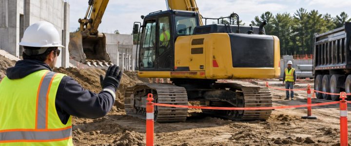
Horizontal directional drilling (HDD) can install pipe, conduit, and cable with less surface disruption than open-cut construction. It also places a drill head, steering tools, reaming equipment, and product pipe into ground conditions that may not be fully known. Before a pilot bore begins, the project team needs dependable information about utilities near the proposed alignment, entry pit, exit pit, and crossing points.
That is where vacuum excavation for directional drilling becomes valuable. A planned utility daylighting program can physically expose selected utilities so their observed position, depth, size, material, and configuration can be documented. This gives engineers and contractors more useful information than utility records or geophysical indications alone when clearance is tight or the consequences of a utility strike are significant.
Vacuum excavation does not make an HDD project risk-free, and not every utility can be exposed everywhere along a bore route. It is a targeted investigation method. Used with records research, 811 coordination where applicable, private utility locating, Subsurface Utility Engineering (SUE), survey control, and a sound drilling plan, utility test holes can help the team make better decisions before drilling starts.
Why HDD projects need physical utility verification
Plans, as-builts, and utility owner records are important starting points, but they should not be treated as proof of current field conditions. A utility may have been installed at a different depth or alignment than shown. Later roadway work, site grading, repairs, abandoned lines, added conduits, settlement, or incomplete records can further complicate the picture.
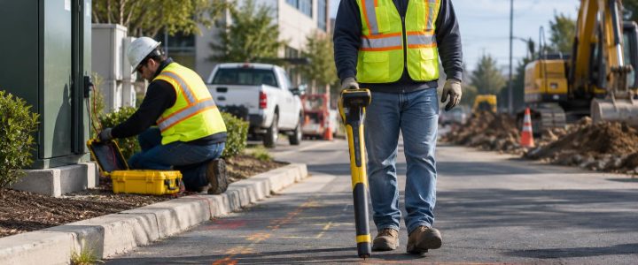
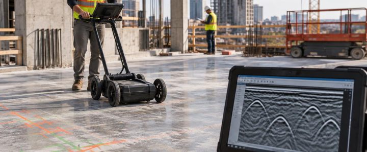
Electromagnetic (EM) locating and ground penetrating radar (GPR) can provide valuable evidence of an underground utility’s interpreted route. Those methods are often appropriate for identifying likely conflicts and selecting investigation areas. However, a signal response or GPR interpretation may not provide the level of certainty needed to set an HDD profile near a critical crossing.
Physical utility exposure can allow the field team to observe what is actually present at a specific location. Depending on safe access and the extent of exposure, a test hole may help confirm:
- The utility’s observed horizontal position at the test-hole location.
- Depth measured from an established surface reference to the exposed utility.
- Top, centerline, or invert information when the measurement basis is clearly stated.
- Pipe outside diameter or the dimensions of a duct bank, casing, or conduit group.
- Observable material, such as steel, plastic, clay, concrete, or ductile iron.
- The number and arrangement of visible conduits or cables.
- Whether two utilities cross and their observed vertical separation at that point.
- Visible protective features, including casings, concrete encasement, tracer wire, or warning tape.
These observations can identify a conflict that needs a revised bore path, additional clearance review, utility-owner coordination, or a different installation method.
Utility locating is not the same as utility verification
A locate mark or geophysical designation is useful information, but it is not the same as physical verification. For HDD planning, the difference matters.
What locating and records can provide
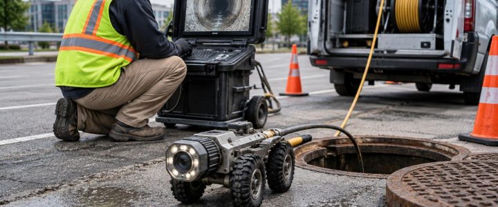
Utility records, visual site evidence, EM locating, and GPR may indicate that a utility is present and help establish its likely route. An estimated depth may sometimes be derived from a locating method, but it remains an estimate affected by signal conditions, access, soil, utility configuration, and field assumptions.
What a vacuum-excavated test hole can provide
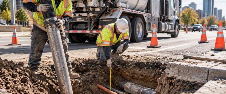
A test hole physically exposes the utility at a defined point. The investigator can then observe and document characteristics that are not reliably determined by an EM signal or GPR response alone. If the project needs design-ready coordinates or elevations, the exposed utility must also be measured or surveyed using appropriate procedures and a clear project datum.
In other words, vacuum excavation can expose the asset, but it does not automatically create a surveyed elevation. A depth measurement might be adequate for a field decision. A civil design profile, utility relocation plan, or engineered clearance review may require a surveyor to collect horizontal and vertical coordinates tied to project control.
How Quality Level B and Quality Level A relate to an HDD investigation
ASCE 38-22 describes a framework for investigating and documenting existing subsurface utilities. In general terms, Quality Level B involves the application of appropriate surface geophysical methods to designate the horizontal position of subsurface utilities. Quality Level A involves exposing a utility at a point and obtaining precise information through measurement and documentation.
For an HDD project, Quality Level B information can help identify potential conflicts along the proposed route. Carefully selected test holes can then be used where physical confirmation is needed, such as at a major crossing, a congested corridor, a shallow utility, an entry or exit area, or a location where the proposed bore profile has limited room.
Not every daylighting effort automatically meets all requirements for Quality Level A. The investigation scope, field procedures, measurement method, survey control, documentation, and project requirements all matter. Project teams that need formal SUE deliverables should define those requirements before fieldwork begins. Visionary Subsurface Solutions can coordinate vacuum excavation with Subsurface Utility Engineering and QL-B investigation services when a planned, integrated approach is needed.
Where to place test holes before directional drilling
Random potholes can consume time without answering the questions that control the bore design. A stronger approach is to select locations based on the proposed HDD alignment, expected drill profile, available utility information, site access, and the consequence of an incorrect assumption.
High-value daylighting locations
- Known or suspected utility crossings: Expose the existing utility where the proposed bore will pass near or below it. This can help establish whether the planned vertical separation is realistic.
- Entry and exit areas: Verify utilities near drilling equipment, pits, tie-in locations, and proposed product-pipe staging areas.
- Congested corridors: Investigate locations where several designated utilities appear to occupy a narrow band.
- Profile changes: Consider test holes where the designed bore changes depth or where a utility creates a critical restriction.
- Uncertain records: Prioritize utilities shown inconsistently across record drawings, prior surveys, or design documents.
- High-consequence infrastructure: Use a project-specific investigation plan around major electric, gas, communications, water, sewer, transit, or industrial systems.
- Potential return-path concerns: Review utilities and structures near locations where drilling-fluid returns could create a problem.
The number of utility test holes depends on the route length, congestion, proposed depth, available records, design tolerance, and risk. There is no universal spacing rule that fits every HDD project. The appropriate question is: which unknowns could materially change the drilling plan, and where can a test hole resolve them?
What to record after daylighting a utility
The value of a utility pothole is limited if the findings are not captured in a form the design and construction teams can use. Before excavation, agree on the information required, the measurement reference, photo requirements, survey needs, and deliverable format.
A practical utility test-hole record commonly includes:
- Project name, date, test-hole identifier, and field personnel.
- Test-hole location and relationship to the proposed bore alignment.
- Surface reference or project control used for measurements.
- Observed utility type and visible material.
- Observed outside diameter, conduit count, duct-bank dimensions, or casing details when visible and safely measurable.
- Depth measurements with the stated reference point, such as top of utility or top of casing.
- Surveyed coordinates and elevations when required by the project.
- Observed horizontal offset from the proposed HDD alignment.
- Crossing utility information and observed vertical separation, when applicable.
- Photographs, sketches, and notes on visible appurtenances, encasement, condition, or access limitations.
- Whether the excavation was backfilled and surface restoration requirements.
Measurements should be clearly labeled. For example, “7.2 feet to top of pipe from existing pavement surface” is more useful than a note that simply says “depth: 7.2 feet.” It avoids confusion when teams later compare test-hole findings to a bore profile or survey data.
Hydro excavation and air excavation for HDD test holes
Both hydro excavation and air excavation use a vacuum system to remove loosened soil from the exposure area. The best method depends on site conditions and the project’s material-handling needs.
Hydro excavation
Hydro excavation uses controlled water to loosen soil for vacuum removal. It can be productive in many soil conditions, including cohesive or compacted material. It also creates slurry that must be managed, transported, and disposed of in accordance with project and site-specific requirements. Groundwater, cold weather, pavement restoration, available water, and environmental controls can affect feasibility.
Air excavation
Air excavation uses compressed air to loosen soil for vacuum removal. It may be useful where avoiding added water is important or where dry spoils are easier to manage. Performance can vary with soil type, moisture, compaction, and cobbles. Air excavation may also require careful dust and debris control based on conditions.
Neither method is universally better. The field approach should account for the utility type, soil, depth, available workspace, traffic control, restoration needs, disposal plan, weather, and utility-owner or facility requirements.
Field controls still matter around exposed utilities
Vacuum excavation is often selected as a non-destructive excavation method because it can reduce reliance on mechanical digging immediately around known or suspected utilities. That does not eliminate the need for planning and qualified operation. The work remains active excavation around potentially hazardous infrastructure.
Before work begins, the team should address locating status, permits and notifications as applicable, work-zone controls, equipment setup, vacuum hose management, overhead hazards, spoil or slurry handling, access, emergency procedures, and restoration. The crew also needs a defined stopping point: if the observed utility differs materially from the expected condition, drilling should not proceed on assumption alone.
Common HDD daylighting mistakes to avoid
- Using a single test hole to represent an entire utility route: A line can change depth or direction between exposure points.
- Failing to tie findings to the proposed bore: A utility depth is less useful without knowing its offset and relationship to the HDD profile.
- Recording an unlabeled depth: State the reference surface and whether the measurement is to the top, centerline, invert, or bottom of the utility.
- Assuming an exposed pipe tells the full story: Nearby abandoned lines, parallel conduits, duct-bank extensions, and service laterals may still require investigation.
- Skipping survey when precise design data is needed: Physical exposure and surveyed location are related but separate tasks.
- Leaving findings in field notes only: Share documented results with the engineer, HDD contractor, superintendent, and other decision-makers before drilling.
Frequently asked questions
Does a utility test hole confirm the exact depth of a utility?
It can confirm a measured depth at the exposed location when the measurement reference is documented. Depth may change along the utility route, so one test hole should not be assumed to establish the utility’s depth everywhere.
Can vacuum excavation confirm utility material and size?
Physical exposure can allow visible material and outside dimensions to be observed and documented. The extent of confirmation depends on how much of the utility can be safely exposed, whether it is encased or in a duct bank, and whether dimensions are accessible for measurement.
Do HDD projects need surveyed utility elevations?
Not every project needs a formal survey, but survey data is often appropriate when the bore design depends on precise vertical clearance, project control, or a design profile. The project engineer and survey team should establish the required accuracy and datum.
When should utility locating be followed by vacuum excavation?
Follow locating with physical verification when an identified or suspected utility could affect the bore path, when records are uncertain, when vertical separation is critical, or when the project needs information that locating alone cannot reliably establish.
Plan daylighting before the drill rig arrives
A utility daylighting plan is most useful when it supports a specific decision: adjust the bore profile, confirm a crossing, select an entry point, coordinate with a utility owner, or establish field controls for drilling near an existing line. Bringing the HDD contractor, engineer, locator, surveyor, and vacuum excavation team into that plan early can reduce last-minute uncertainty at the drill site.
For projects in Pennsylvania, New Jersey, Delaware, Maryland, New York, or the Washington, D.C. to New York City corridor, contact Visionary Subsurface Solutions to discuss vacuum excavation and QL-A utility exposure for your HDD investigation, utility crossing verification, or preconstruction planning needs.
Technical references
For the Quality Level framework discussed here, see the ASCE 38-22 standard information and the Federal Highway Administration’s overview of Subsurface Utility Engineering. Project specifications, utility-owner requirements, and site conditions should guide the final investigation scope.