Vacuum excavation can physically expose an underground utility, but the value of a test hole depends on what happens next. If the crew simply confirms that a line is present and backfills the opening, important information for design and construction can still be missing.
Good utility test hole documentation turns a daylighted utility into usable project information. It helps engineers assess conflicts, lets surveyors tie observations to the project control system, and gives contractors clearer direction before larger excavation begins. It can also reveal when plans, utility records, or geophysical markings do not match the field condition.
For projects involving tight clearances, proposed grading, new foundations, utility relocations, or directional drilling, a planned test-hole program can reduce uncertainty at the locations where it matters most. The goal is not to dig random holes. The goal is to expose selected utilities safely and document the facts needed to make a decision.
What a properly documented test hole can verify
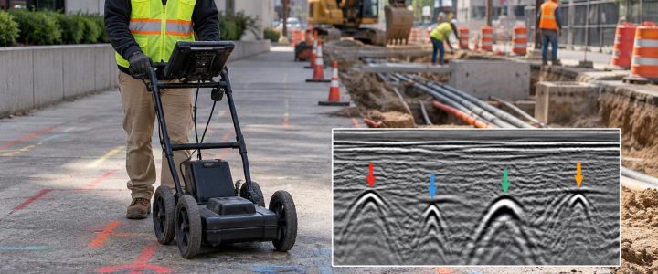
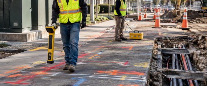
Electromagnetic locating and ground penetrating radar can help designate a probable utility route or provide an interpreted depth estimate. Those methods are important for planning an investigation, but they do not provide the same level of direct observation as physical exposure.
Once a utility has been daylighted with hydro excavation or air excavation, qualified personnel may be able to observe and document characteristics such as:
- The utility’s actual exposed horizontal position
- Measured depth from the existing surface or another clearly identified reference point
- Top, centerline, or invert measurement, depending on the utility and project need
- Outside diameter or approximate dimensions of an exposed pipe, duct bank, conduit, or casing
- Observable material, such as steel, plastic, concrete, clay, or metallic conduit
- The number and arrangement of visible conduits
- Visible casing, encasement, tracer wire, warning tape, or protective features
- The relationship between utilities at a crossing or conflict point
- Observable condition concerns, where safely visible, such as deformation, damaged coating, leakage indicators, or abandoned components
Physical exposure does not mean every characteristic can be confirmed in every hole. A line may only be visible over a limited area, may be within a congested duct bank, or may be obstructed by groundwater or unstable soil. The documentation should clearly state what was observed, what was measured, and what remains unknown.
Depth, elevation, and location are not the same thing
These terms are often used interchangeably in field discussions, but they serve different purposes in design and construction.
Estimated depth from locating
An electromagnetic locator may provide an estimated depth under suitable conditions. That estimate can be affected by signal distortion, nearby conductors, utility configuration, soil conditions, and the assumptions used by the instrument. It is helpful for planning, but it should not automatically be treated as a verified construction elevation.
Measured depth after daylighting
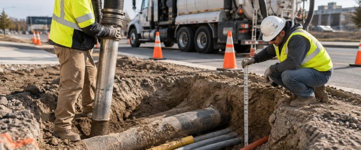
After utility exposure, the crew can measure the vertical distance from a defined surface reference to the top, centerline, or invert of the utility. The record should identify both the reference point and the feature measured. For example, “5.2 feet below existing pavement to top of 8-inch pipe” is clearer than “depth: 5.2 feet.”
Surveyed utility elevation
A surveyed elevation requires appropriate project control, survey procedures, and a clearly identified point on the exposed utility. If the design team needs a reliable coordinate and elevation for a profile, conflict analysis, or relocation plan, the test hole should be coordinated with the survey team before excavation begins.
Vacuum excavation exposes the feature that needs to be measured; it does not automatically create a surveyed elevation. A test-hole request should state whether simple field measurements are sufficient or whether horizontal coordinates and vertical elevations must be surveyed.
Why records and plans may not match field conditions
Utility plans and historical records are valuable starting points, but they may not represent current, as-built field conditions. A utility may have been installed differently than planned, moved during later work, repaired with a different material, or affected by roadway reconstruction and site redevelopment. Some private utility records may also be incomplete.
A discrepancy is not necessarily an error by one party. It is a field condition that needs to be understood before design or excavation proceeds. The test-hole record should compare the observed location with the available plans, markings, and design assumptions without assigning ownership or cause unless that information has been independently verified.
When a discrepancy affects a proposed structure, trench, bore path, or utility connection, the project team may need additional test holes, updated utility designations, survey work, or a revised construction approach.
A practical utility test hole documentation checklist
Before fieldwork, the project team should agree on the data needed from each exposure. The following checklist provides a practical starting point for utility potholing services and SUE test holes.
1. Identify the test hole clearly
- Project name, location, date, and unique test-hole identification number
- Street address, station and offset, grid reference, or other project-specific location reference
- Purpose of the hole, such as verifying a proposed water-line crossing or confirming clearance for a foundation
- Existing surface condition, including pavement, lawn, sidewalk, shoulder, or landscaped area
2. Record the investigation basis
- Available utility records, plans, or design sheets reviewed for the location
- Surface markings observed before excavation
- Private utility locating or SUE designation information used to select the location
- Known limitations, such as congestion, restricted access, traffic, or incomplete records
For a planned subsurface investigation, test holes often follow utility designation work. Visionary Subsurface Solutions can coordinate Subsurface Utility Engineering and QL-B services with physical exposure where the project needs additional confidence at specific points.
3. Document the exposed utility itself
- Utility type, if known from records, markings, owner information, or observable features
- Observed material and outside diameter or dimensions
- Number of lines, conduits, or ducts observed
- Configuration, including stacked conduits, duct-bank arrangement, casing, or crossing geometry
- Visible appurtenances or protection, such as warning tape, tracer wire, encasement, or concrete protection
- Any visible condition observations, stated carefully and limited to what was exposed
A physical observation of material or configuration should not be confused with confirmation of ownership, service status, pressure, voltage, or operational condition. Those questions may require utility-owner coordination, facility records, or other qualified investigation.
4. Capture the measurements that support the decision
- Depth reference used and the point on the utility measured
- Top, centerline, bottom, or invert measurement, as applicable
- Horizontal offset from a defined feature or project baseline
- Vertical separation at a utility crossing
- Survey coordinates and elevations when included in the scope
- Dimensions of the excavation where relevant to restoration or constructability
At a crossing, one number is rarely enough. The documentation should identify both utilities, the points measured on each, the reference used, and whether the stated clearance is vertical, horizontal, or both.
5. Take useful photographs
Photographs are most helpful when they provide context. Include a scale, labeled marker, or measuring device where appropriate. Capture the exposed utility, the surrounding configuration, and an overview showing the hole location. Photos should be linked to the test-hole identification number and kept with the field record.
How test-hole information supports Quality Level A investigations
In Subsurface Utility Engineering, Quality Level B generally refers to geophysical designation of utilities, while Quality Level A involves the highest level of accuracy obtained through physical exposure and measurement at selected points. ASCE 38-22 describes the framework for collecting and depicting existing subsurface utility data, and the Federal Highway Administration also recognizes SUE as a process for managing utility uncertainty during project development.
Not every daylighting operation automatically delivers Quality Level A information. The result depends on the scope, field methods, measurements, survey control, documentation, and how the work is performed and reported. A contractor or engineer should define the required deliverable before mobilization rather than assuming any exposed utility will satisfy the needs of a particular standard or design decision.
For project teams seeking a formal SUE deliverable, review the applicable project requirements and the current ASCE 38-22 standard. FHWA guidance on Subsurface Utility Engineering also provides useful context for incorporating utility information into transportation and infrastructure planning.
When to specify utility test holes
Engineers and contractors should consider utility exposure when the answer will change the design, method, sequence, or cost-risk decision. Common triggers include:
- A proposed utility crosses an existing line and required vertical clearance is uncertain.
- A roadway, foundation, retaining wall, or structure is close to a designated utility.
- A directional drilling profile passes near known or suspected infrastructure.
- Plans show conflicting locations, sizes, or elevations.
- A private utility must be confirmed before trenching, sawcutting, or excavation.
- Utility relocation design requires actual pipe size, material, configuration, or cover information.
- A congested corridor leaves little room to adjust construction after work begins.
Test holes are particularly valuable before finalizing a design profile or releasing a high-risk excavation package. They can also be used during construction when field conditions differ from the plan. However, late investigation may leave fewer options, so early coordination is usually more useful.
Planning the work: practical limits and field controls
Vacuum excavation is a non-destructive excavation approach intended to reduce the risk associated with mechanical digging around known or suspected utilities. It still requires careful planning and experienced operation. Appropriate methods vary by site.
Hydro excavation uses pressurized water to loosen soil and a vacuum system to remove the spoil. Air excavation uses compressed air for soil breakup and vacuum removal. Hydro excavation may be effective in many soil conditions, while air excavation can be useful where minimizing added water is important. The appropriate choice can depend on soil type, utility sensitivity, groundwater, restoration requirements, environmental constraints, and spoil or slurry disposal options.
Other practical issues include frozen ground, traffic control, work-zone space, access for the vacuum truck, overhead clearance, utility congestion, excavation depth, surface restoration, groundwater management, and site-specific disposal requirements. No vacuum excavation method is risk-free. Utility markings, job hazard analysis, appropriate nozzles and pressures, controlled excavation techniques, and qualified crews remain essential.
Make the final record usable in the field
A strong final deliverable should be easy for both the design office and the field superintendent to understand. It should include a concise test-hole log, labeled photographs, measurement references, any survey data requested, and a clear note of limitations or unresolved conditions.
Before backfill, the crew and project representative should confirm that the needed observations, measurements, and photographs have been completed. Once the hole is restored, returning to verify a missed detail can delay the project and add cost.
Visionary Subsurface Solutions provides vacuum excavation and QL-A utility exposure services for projects throughout Pennsylvania, New Jersey, Delaware, Maryland, New York, and the Washington, D.C. to New York City corridor. Contact our team to discuss the utility information your design or construction project needs and how a targeted test-hole program can help obtain it.