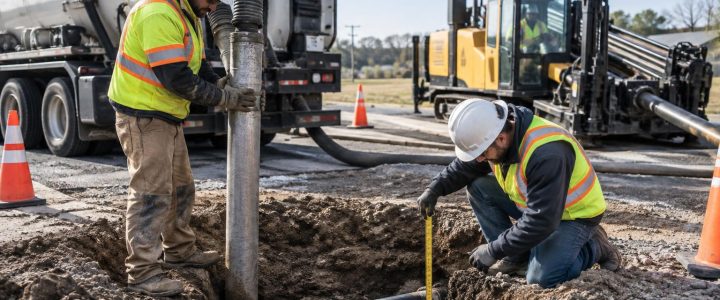
Utility plans, as-builts, 811 markings, private utility locating, and Ground Penetrating Radar (GPR) can all provide useful information before design or excavation. They should not, however, be treated as automatic proof of what is in the ground. When a project decision depends on a utility’s actual position, depth, elevation, size, material, or configuration, planned utility test hole services may be the appropriate next step.
Vacuum excavation gives the project team a controlled way to physically expose a known or suspected utility. The exposed utility can then be observed, measured, photographed, and, when needed, surveyed. This is often more useful than making a design or construction decision based only on records or an interpreted geophysical signal.
The goal is not to pothole every marked line on a site. The goal is to identify the locations where uncertain utility information creates a meaningful design, safety, schedule, or constructability risk—and then verify those locations before the risk becomes an excavation conflict.
Why records and plans can differ from field conditions
Utility records are important references, but they may describe intended installation rather than confirmed final placement. Older drawings may be incomplete, based on different site control, or limited to a general route. Private utility work, repairs, abandoned lines, roadway reconstruction, settlement, utility relocations, and undocumented connections can further complicate the picture.
A line shown on a utility plan may be close to its actual route but still be too uncertain for a proposed footing, storm structure, trench, bore path, or tie-in. A depth listed in a record may also be a design value, a historical measurement, or an estimate—not a current field measurement at the point that matters to the project.
That is why project teams should separate three different types of information:
- Records information: utility plans, as-builts, maps, and owner-provided data.
- Geophysically designated information: an interpreted horizontal utility position developed through electromagnetic locating, GPR, or other methods.
- Physically verified information: characteristics observed after carefully exposing the utility, with measurements and survey control added when required.
Each has value. The question is whether the planned work can safely proceed with the level of certainty currently available.
Utility locating is not the same as utility verification
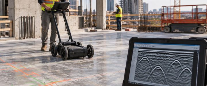
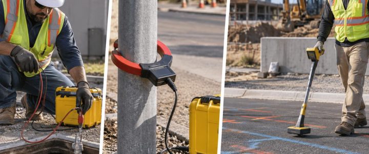
Private utility locating and SUE investigations can identify and trace many utilities without excavation. Electromagnetic methods can be highly effective on accessible conductive lines or trace wires. GPR can sometimes identify subsurface anomalies or utilities, particularly where site conditions support a usable signal. These methods help build a practical picture of the site and target higher-risk areas for further investigation.
But a marked line or interpreted signal does not always establish the exact centerline, depth, elevation, outside diameter, material, number of conduits, casing arrangement, or physical condition of a utility. Congested corridors, poor access, non-metallic pipes, inactive lines, reinforced concrete, nearby interference, soil conditions, and unknown installations can all affect the result.
Vacuum excavation for utilities changes the investigation from interpretation to observation. Once the utility is safely exposed, the field team can confirm the visible characteristics that matter to the decision at hand. For coordinated investigations, private utility locating can help establish likely routes before a test-hole plan is developed.
When should engineers and contractors specify test holes?
A test hole is most valuable when the consequence of being wrong is high. Consider utility daylighting when one or more of the following conditions applies:
- A proposed storm, sanitary, water, gas, electric, or communications installation is expected to cross an existing utility.
- A foundation, retaining wall, sign base, pole, vault, inlet, or other structure will be placed near a marked utility.
- The design profile depends on confirming an existing utility elevation.
- Two utilities appear to cross, but their vertical separation is unknown.
- Utility records conflict with each other or with field markings.
- A utility’s size, pipe material, conduit bank configuration, or casing must be confirmed before final design.
- A directional drilling path needs clearance information at crossings, entry points, exit points, or congested areas.
- A contractor needs to expose a utility before conventional excavation can approach it.
- A utility is shown within a proposed work area, but its depth is unknown or unsuitable for the intended work.
- Design changes, field discoveries, or owner comments have created a new utility conflict late in the project.
For example, a proposed storm sewer may appear clear of a marked communications route in plan view. If the two lines cross near a proposed structure, the key unanswered question is often vertical separation. A properly located test hole can help establish whether the design needs to shift, whether protection is required, or whether the apparent conflict is not a conflict at all.
A practical framework for selecting test-hole locations
Random potholing can add cost without resolving the project’s actual unknowns. A better approach is to create a targeted test-hole plan that connects each hole to a specific design or construction question.
1. Define the decision that needs support
Start with the question, not the equipment. Examples include: Can the proposed water line pass below the existing duct bank? Is the gas main deep enough to clear a proposed footing? Does the apparent crossing occur where the plans show it? Is the existing pipe a single line, a casing, or a multi-conduit installation?
2. Review available information together
Compare design drawings, utility owner records, previous locates, site observations, survey data, and available SUE information. Note conflicts rather than forcing one source to be treated as correct. The review should identify the areas where field verification could change the design or construction approach.
3. Use non-destructive investigation to refine targets
Electromagnetic locating, GPR, and surface features can help refine a suspected utility route before excavation. This supports efficient test-hole placement and reduces unnecessary surface disturbance. It also helps the team account for parallel utilities and possible crossings in congested corridors.
4. Place holes at decision points
Useful locations often include anticipated crossings, points where a proposed line changes grade, utility tie-in locations, bore-path conflict points, structure corners, and locations where records indicate a material or size change. One test hole may not represent an entire utility corridor. A line can change depth, alignment, or configuration between exposures.
5. Coordinate surveying before fieldwork begins
If the design requires precise coordinates or elevations, arrange survey control and establish what must be captured before the hole is excavated. A depth measurement after exposure is valuable, but it is not automatically a surveyed elevation. Survey procedures and appropriate project control are needed when the design team requires reliable horizontal and vertical coordinates.
What a vacuum excavation test hole can verify
When site conditions allow safe exposure, utility potholing can provide direct observations that are difficult to obtain from records or geophysical designation alone. The project team may be able to document:
- The utility’s observed horizontal position at the exposure point.
- Depth below the existing surface, measured after exposure.
- Surveyed elevation of the exposed utility when survey control and procedures are used.
- Visible pipe or conduit size, including outside diameter where accessible and appropriate to measure.
- Observable material, such as metallic pipe, plastic pipe, concrete, clay, or conduit components.
- The number and arrangement of visible conduits or duct-bank components.
- Whether a visible line is within a casing or shares a corridor with other facilities.
- Vertical separation at an exposed crossing.
- Site conditions affecting constructability, including congestion, obstructions, or difficult access.
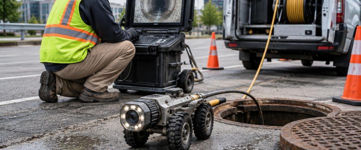
Physical exposure does not answer every question. The full alignment, condition, ownership, internal diameter, operational status, and complete extent of a utility may still require records review, owner coordination, CCTV inspection, additional test holes, or other investigation methods.
How QL-B and QL-A information work together
In Subsurface Utility Engineering, Quality Level B generally refers to the application of appropriate surface geophysical methods to designate the horizontal position of subsurface utilities. Quality Level A involves exposing a utility at discrete points to obtain precise information through measurement and documentation. The ASCE 38-22 standard provides the current framework for investigating and documenting existing subsurface utility information.
Quality Level A is not simply “digging a hole.” The final quality of the information depends on the planned investigation, methods used, measurements, survey control where needed, documentation, and how the results are conveyed to the project team. The Federal Highway Administration likewise describes SUE as a process that combines records research, geophysics, and test holes to manage utility uncertainty during project development.
Not every vacuum excavation project is a complete SUE investigation, and not every daylighted utility automatically meets every Quality Level A requirement. Still, vacuum excavation is a common means of physically exposing utilities when a planned SUE or utility verification effort calls for that level of field confirmation.
Hydro excavation and air excavation: choose the method for the site
Both hydro excavation and air excavation use a vacuum system to remove loosened soil from around buried infrastructure. The best method depends on the utility, soil, restoration requirements, available disposal options, weather, groundwater, and project constraints.
Hydro excavation
Hydro excavation uses pressurized water to break up soil while a vacuum removes the resulting slurry. It can be effective in compacted soils and can support productive utility exposure in many conditions. The slurry must be managed and disposed of in accordance with site-specific requirements, and water use, freezing temperatures, surface restoration, and environmental controls should be considered during planning.
Air excavation
Air excavation uses compressed air to loosen soil for vacuum removal. It can produce dry spoil that may be easier to manage or reuse where appropriate. In dense clay, wet soil, rocky conditions, or frozen ground, production and suitability may differ. Air excavation can also create dust and requires appropriate controls for the work area.
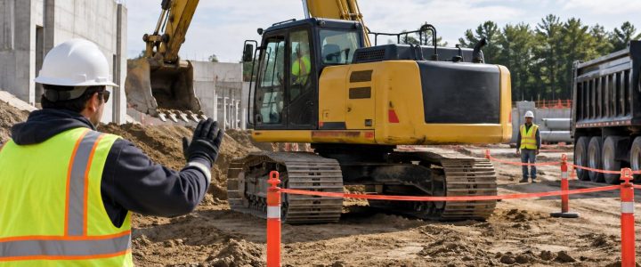
Neither approach is risk-free or universally better. Qualified operators, appropriate nozzle techniques, utility locating, controlled excavation, work-zone protection, and clear communication remain essential. Vacuum excavation is intended to reduce the risk associated with mechanical digging around known or suspected utilities, not eliminate the need for planning and safe excavation practices.
Documentation that makes a test hole useful after the crew leaves
A daylighted utility is most valuable when the field result becomes usable project information. Before work begins, establish the reporting format and confirm who needs the results: designer, surveyor, owner representative, utility coordinator, contractor, or field superintendent.
Depending on the project, useful documentation can include:
- Test-hole identification number and date.
- Location referenced to project control or a clear field reference.
- Photographs showing the exposed facility and measurement setup.
- Observed utility type, material, size, configuration, and condition notes.
- Measured depth from the existing surface at the exposure point.
- Surveyed horizontal and vertical information, when requested and properly collected.
- Crossing relationships and measured vertical separation, if exposed.
- Notes about obstructions, groundwater, unstable soils, traffic constraints, or incomplete exposure.
- A statement of what was observed at that point and any remaining limitations.
This record allows the design and construction teams to compare verified conditions against utility records and design assumptions. It can also reduce the chance that critical field knowledge is lost between the investigation phase and active construction.
Common test-hole planning mistakes
- Waiting until the trench is open: Verification may still help, but late discoveries can force costly redesigns, downtime, or emergency coordination.
- Using one hole to represent a long run: Utility grade and alignment can change between exposure points.
- Requesting “depth” without defining the reference: Clarify whether the project needs a field depth from surface or a surveyed elevation tied to project datum.
- Ignoring access and traffic control: A technically good test-hole location may require lane closures, permits, restoration planning, or alternate work windows.
- Failing to plan spoil or slurry handling: Disposal, containment, and restoration requirements should be addressed before mobilization.
- Assuming exposure establishes ownership or operational status: Those questions typically require records review and coordination with the relevant owner or operator.
FAQ: Utility test holes and physical verification
Do utility test holes guarantee that every utility will be found?
No. A test hole verifies conditions at a specific exposure point. It should be part of a planned investigation that considers records, locating results, site conditions, and the limits of the work area.
Can a test hole confirm a utility’s exact elevation?
Physical exposure allows the utility to be measured. If exact design coordinates or elevations are needed, the exposed point should be surveyed or measured using project-appropriate procedures and control. A simple depth measurement is not the same as a surveyed elevation.
When should a locate be followed by utility daylighting?
Follow locating with physical verification when the project depends on information that a surface designation cannot reliably provide, such as vertical separation, actual depth, size, material, conduit configuration, or a conflict point near proposed excavation or construction.
Plan verification before uncertainty becomes a field problem
The best time to resolve a utility conflict is usually before final design is locked in or excavation begins. Targeted vacuum excavation test holes can turn uncertain records and surface marks into field observations that support safer, more constructible decisions.
Visionary Subsurface Solutions provides vacuum excavation and QL-A utility verification services throughout Pennsylvania, New Jersey, Delaware, Maryland, New York, and the Washington, D.C. to New York City corridor. Contact our team to discuss a test-hole plan that fits your utility coordination, design, or construction needs.