When a proposed storm line, foundation, duct bank, roadway profile, or directional drill path must pass near an existing utility, horizontal utility marks are only part of the answer. The project team also needs to know what is happening vertically: Is the utility actually at the depth shown on a record drawing? Does it cross above or below another line? Is there enough clearance for the proposed work?
Utility elevation verification uses physical exposure, careful measurement, and, when required, survey control to establish more reliable information about an existing utility’s position. Vacuum excavation is often the practical method for creating the small, controlled test holes needed to expose the utility without relying on conventional mechanical digging immediately beside it.
This process can help engineers refine a design before it reaches construction and help contractors avoid discovering a conflict only after an excavation is open.
Why estimated depth is not the same as verified elevation
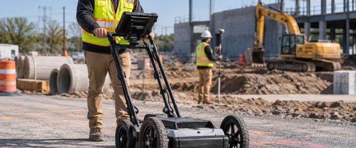
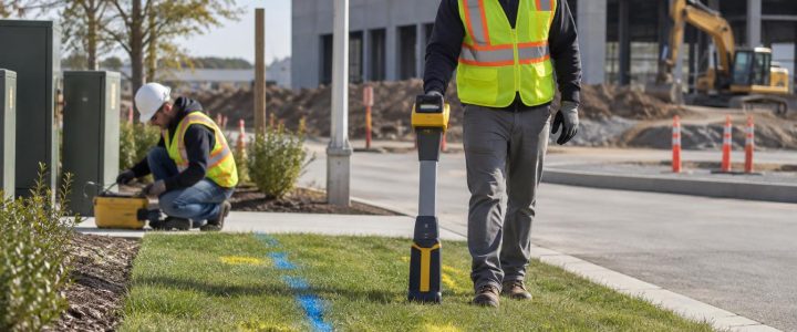
Utility locating methods provide valuable information, but they do not all answer the same question. Electromagnetic locating can trace a conductive line or a traceable utility and may provide an estimated depth. Ground penetrating radar may identify subsurface anomalies or interpreted utility positions in suitable conditions. Both methods can guide an investigation, but neither automatically confirms the exact physical position or elevation of every underground utility.
For design and construction decisions, it is useful to separate three different levels of information:
- Estimated depth: A depth estimate obtained through a locating method. It can be affected by signal distortion, congestion, soil conditions, utility configuration, and the quality of the available signal.
- Measured depth after exposure: The distance measured from a known surface reference to the physically exposed utility at a specific location.
- Surveyed utility elevation: A horizontal and vertical coordinate collected using appropriate survey control and procedures after the utility has been exposed.
A vacuum excavation test hole can expose the asset so its position and observable characteristics can be measured. It does not, by itself, create a surveyed elevation. If the design needs reliable coordinates, a surveyor or qualified field team should tie the exposed utility to the project control system and clearly identify the point being measured.
When utility elevation verification is worth planning
Not every marked utility needs a test hole. Physical verification is most useful where an incorrect assumption could change the design, construction method, sequence, or risk profile. Engineers and contractors commonly request utility test hole services in the following situations.
A proposed utility has a tight vertical clearance
Small differences in elevation can matter where a proposed gravity sewer, drainage structure, water line, or electrical duct bank must pass over or under an existing facility. A plan-view crossing does not establish vertical separation. Daylighting one or both utilities near the crossing can help the team determine whether the planned clearance is available.
Existing records conflict or lack key details
Record drawings may show an approximate route without an invert elevation, pipe outside diameter, casing information, or a dependable installation depth. Older sites may also have multiple rounds of construction, abandoned facilities, undocumented repairs, or utility relocations. These records remain useful starting points, but field conditions should not be assumed to match them without investigation.
A design profile depends on the actual utility position
Roadway reconstruction, site grading, drainage improvements, and utility relocation work often depend on a usable vertical profile. A few properly located test holes at critical points can give the designer field-based information before finalizing grades, structures, or relocation concepts.
Construction will excavate close to a known or suspected utility
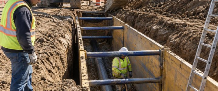
Before trenching, drilling, installing shoring, or excavating for foundations, a contractor may need to daylight underground utilities within or near the work area. Utility exposure gives the crew a visual reference for the actual utility at that location and can support a safer excavation approach. It does not eliminate the need for a site-specific excavation plan, appropriate support of excavation, and safe work practices.
An HDD bore path needs confirmation at crossings
For horizontal directional drilling, surface marks and estimated depths may not provide enough confidence at critical crossings. Vacuum excavation for utilities can expose selected facilities so the HDD team can better understand the crossing location, observed depth, and available separation before the pilot bore begins.
How vacuum excavation supports utility elevation verification
Vacuum excavation removes loosened soil using air or water and a high-powered vacuum system. Hydro excavation uses controlled water to break up soil before removal. Air excavation uses compressed air instead. Both can be used for non-destructive excavation around known or suspected utilities when selected and operated for the site conditions.
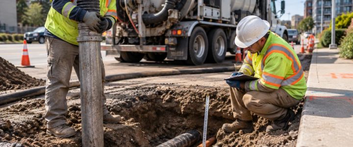
The objective is not simply to create a hole. It is to expose enough of the utility to observe the relevant feature safely and document it clearly. Depending on the assignment, that may mean exposing the crown of a pipe, the top of a duct bank, the top and bottom of a conduit, a utility crossing, or another defined point.
Once exposed, the field team may be able to observe and document:
- Actual horizontal position at the test-hole location
- Depth to the top, centerline, invert, or another specified reference point
- Utility type, where it can be identified from visible characteristics or project information
- Pipe outside diameter or visible conduit size
- Pipe or conduit material that is physically observable
- Number and arrangement of visible conduits
- Casing, encasement, duct bank, tracer wire, or other observable configuration details
- Relative vertical separation where two utilities are exposed at a crossing
- Site conditions that may affect construction access or excavation methods
Physical exposure provides direct observations at that location. It should not be treated as proof that the utility has the same depth, material, or configuration throughout the entire site. Utilities can change direction, slope, depth, or configuration between test holes.
From locating to Quality Level A information
Subsurface Utility Engineering, or SUE, is a structured process for investigating and managing utility information. In the ASCE 38-22 framework, Quality Level B generally involves geophysical methods used to designate the horizontal position of detectable utilities. Quality Level A involves the highest level of accuracy, obtained through the physical exposure and precise measurement of a utility at test-hole locations.
That distinction matters. A paint mark or geophysical designation can be highly useful for planning test-hole locations. A daylighted utility can provide direct observations and measurements. But a test hole does not automatically make an entire project a SUE investigation or automatically satisfy every Quality Level A requirement. The scope, measurement method, survey control, documentation, and quality procedures must match the project’s stated needs.
For background on the standard and the SUE process, teams can review ASCE 38-22 and the Federal Highway Administration’s SUE resources. Both describe the importance of distinguishing geophysical designation from physical exposure and measurement.
On active projects, a planned sequence often works well: begin with records review and utility locating, identify the points where vertical uncertainty affects a decision, perform targeted utility potholing, then survey and document the exposed facilities as needed. Visionary Subsurface Solutions can support this approach through Subsurface Utility Engineering and QL-B services and vacuum excavation and QL-A support.
Choosing test-hole locations for elevation questions
A useful test-hole plan targets decision points rather than spacing holes at random. The design team, survey team, utility coordinator, and contractor should identify which unanswered questions could affect the work.
Common target locations include:
- Proposed crossings: Where a new utility, bore, structure, or excavation passes near an existing line.
- Low-clearance areas: Where the proposed profile leaves little room for elevation error.
- Changes in utility alignment: Near bends, service connections, structures, and transitions where depth may change.
- Known conflict areas: Where utility records, field marks, or previous investigations disagree.
- Construction access points: Where crews need a verified utility location before trenching, boring, or installing support systems.
Before work begins, define the information each hole needs to produce. For example, “expose the top of the existing gas main and obtain a surveyed top-of-pipe elevation” is more actionable than “pothole the gas line.” The request should also identify the desired surface reference, coordinate system, vertical datum, required accuracy, restoration expectations, and any traffic or facility-access constraints.
Field documentation that makes the test hole useful
Utility daylighting becomes more valuable when the observations can be understood later by designers and field crews who were not present. The documentation should be clear about what was actually observed and what was interpreted.
A practical test-hole record may include:
- Test-hole identifier, date, and location reference
- Reason for the exposure and the utility expected at that point
- Utility owner or operator information when known from reliable project sources, separated from field observations
- Observed utility type, material, outside diameter, conduit count, casing, or configuration
- Defined measurement point, such as top of pipe, centerline, invert, or top of duct bank
- Measured depth and, if collected, surveyed horizontal and vertical coordinates
- Observed relationship to nearby utilities or proposed work
- Photographs, sketches, and notes on access or site conditions
- Backfill and surface-restoration information, as appropriate for the site
Clarity is especially important for pipes. “Depth” without a defined reference point can create confusion. The depth to the crown of a 24-inch pipe is not the same as its centerline depth or invert elevation.
Hydro excavation or air excavation for utility exposure?
The method should fit the site rather than follow a one-size-fits-all rule. Hydro excavation can be effective in many soil conditions, including compacted soils, but it generates slurry that requires handling and disposal planning. Air excavation may create a drier spoil stream that can be easier to reuse in some settings, but it can be less productive in certain soils and may require effective dust control.
Access, soil type, groundwater, frozen ground, paving, utility congestion, available restoration area, environmental requirements, and traffic control can all affect the selection. A qualified vacuum excavation contractor can review these factors before mobilization.
Limitations to address before daylighting
Vacuum excavation is intended to reduce the risk associated with mechanical excavation near utilities, not to remove all risk. Utility damage remains possible if work is poorly planned, if a line is misidentified, if excavation is too aggressive, or if site conditions are not understood. Appropriate locating, utility-owner coordination where applicable, trained operators, exclusion zones, work-zone controls, and jobsite safety procedures remain essential.
Project teams should also plan for groundwater, difficult soils, utility congestion, work-zone access, slurry or spoil management, restoration, and weather conditions. In some locations, a small test hole may still require lane controls, permits, facility coordination, or a more detailed excavation plan.
Frequently asked questions about utility elevation verification
Can electromagnetic locating provide a utility elevation?
It may provide an estimated depth for a traceable utility under suitable conditions. That estimate can be useful for screening and planning, but it is not the same as physically exposing and measuring the utility or collecting a surveyed elevation.
Does a vacuum excavation test hole confirm the utility’s depth everywhere?
No. It verifies observations at the exposure point. Utility depth and alignment may change between test holes, especially near structures, bends, crossings, repairs, and grade changes.
What is the best point to survey on an exposed utility?
That depends on the design question. A gravity sewer may require an invert elevation, while clearance planning may require the top of pipe or top of duct bank. Define the measurement point before fieldwork so the result is useful to the designer.
Should test holes be completed before final design?
When existing utility elevation could materially affect the proposed design, completing targeted test holes before final design can help reduce late changes. The appropriate timing and number of holes depend on project risk, complexity, and the decisions that remain unresolved.
Plan utility verification around the decisions that matter
Reliable utility elevation information starts with a clear question: What must the design or construction team know before moving forward? Targeted vacuum excavation, supported by locating and survey control where needed, can turn uncertain utility records and estimated depths into documented field observations.
Visionary Subsurface Solutions provides vacuum excavation services, utility daylighting, and utility test hole support for projects across Pennsylvania, New Jersey, Delaware, Maryland, New York, and the Washington, D.C. to New York City corridor. Contact our team to discuss the utility elevation verification needs, access conditions, and documentation requirements for your project.