Congested utility corridors create a problem that painted marks, record drawings, and estimated depths cannot always solve. A proposed trench, structure, bore path, or tie-in may appear clear on paper, yet the field conditions can include parallel conduits, abandoned lines, unexpected crossings, or utilities installed at elevations that differ from available records.
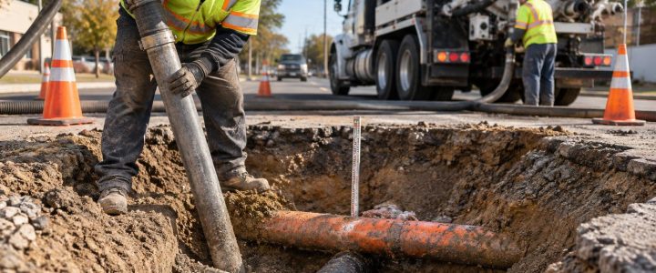
In these situations, utility daylighting uses vacuum excavation to physically expose selected utilities and document what is actually present. It is not a replacement for utility locating or a reason to dig random holes. It is a focused investigation step used when a project needs more reliable information before a design decision or excavation activity proceeds.
For contractors and engineers, the value is practical: a properly planned test hole can help confirm which utility occupies a critical space, whether a crossing has enough separation, and where crews need to adjust their work plan.
Why congested areas need more than utility marks
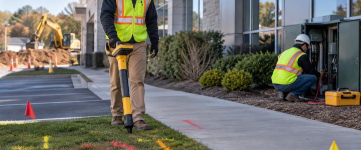
Electromagnetic (EM) locating, ground penetrating radar (GPR), utility records, and visible features all contribute useful information. Together, they can support a working picture of the subsurface. However, each source has limits.
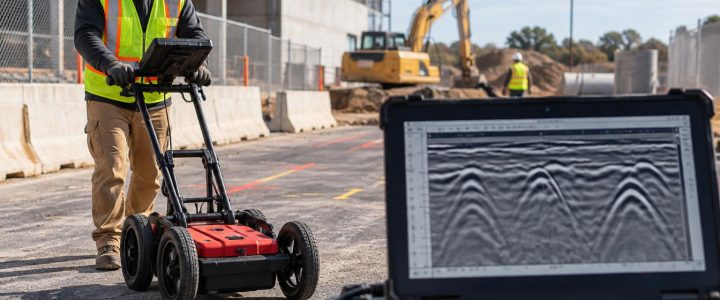
EM locating generally identifies an induced or conducted signal associated with a line. GPR produces an interpretation of subsurface contrasts. Utility records may show intended installation locations, older mapping, or incomplete as-built information. None of these sources alone should automatically be treated as proof of a utility’s actual elevation, outside diameter, construction, or configuration.
Conditions can differ from plans for many reasons:
- A utility may have been installed with field changes that were not fully captured in records.
- Later utility work, roadway reconstruction, or property improvements may have changed the corridor.
- Multiple lines may run close together and affect geophysical interpretation.
- Settlement, regrading, or added pavement sections may change depth measured from the current surface.
- Abandoned utilities, casings, ducts, and unmarked private lines may complicate the picture.
Utility locating provides a designation or interpreted position. Utility verification is different. It involves physically exposing a utility where the project needs direct observation and measurements.
A practical workflow for utility daylighting in congested areas
Effective utility potholing begins with a question that the field team can answer. “Find everything” is rarely a workable scope. “Verify the vertical separation between the marked electric duct bank and proposed storm crossing at Station 12+40” is a useful investigation objective.
1. Define the construction or design decision at risk
Start with the proposed work. Identify where an unknown utility condition could affect the design, schedule, excavation approach, or safety planning. Common examples include:
- A proposed gravity sewer must pass beneath several existing utilities.
- A building addition requires footings near private electric and communications lines.
- A utility contractor needs room for a new conduit bank in an occupied corridor.
- An HDD contractor needs to confirm utilities near an entry pit, exit pit, or sensitive crossing.
- A roadway project needs to determine whether a shallow line conflicts with drainage improvements.
This step helps the team select test-hole locations based on risk and decision value, not just convenient access.
2. Review available information before selecting holes
Bring together utility records, civil drawings, prior locate reports, survey control information, visible structures, and proposed profiles. If a Subsurface Utility Engineering investigation is part of the project, use the Quality Level B designation and other findings to target areas of uncertainty.
Under ASCE 38-22 terminology, Quality Level B relates to the approximate horizontal designation of subsurface utilities using appropriate geophysical methods. Quality Level A involves obtaining detailed information through exposure and measurement at selected points. A vacuum excavation test hole can support a Quality Level A investigation, but a hole alone does not automatically fulfill every project requirement for QL-A documentation, accuracy, survey control, or deliverable format.
For projects that need coordinated designation before exposure, Visionary Subsurface Solutions can support Subsurface Utility Engineering and QL-B investigations as part of a planned workflow.
3. Select test-hole locations that answer specific questions
In a congested corridor, a few well-chosen utility test holes may provide more useful information than many holes placed without a plan. Typical target locations include:
- Proposed utility crossings and conflict points.
- Points where a new utility profile passes near an existing line.
- Changes in alignment, grade, or utility bank configuration.
- Connections near manholes, vaults, pedestals, valves, or risers.
- Locations where multiple design records disagree.
- Areas where marked routes converge or parallel each other closely.
The number of holes depends on utility density, alignment changes, design tolerance, access, and the consequences of being wrong. One hole may confirm a condition at one station but not establish that the same condition continues along the entire route.
4. Plan safe access and excavation controls
Vacuum excavation is intended to reduce the risk associated with mechanical digging around known or suspected infrastructure. It remains active excavation work and needs project-specific planning. The plan may need to address traffic control, utility notifications, work-zone space, overhead hazards, ground conditions, spoil or slurry handling, restoration, and protection of the exposed utility.
Before digging, crews should understand the excavation objective, anticipated utility types, available utility markings, access limitations, and the procedure for stopping work if field conditions do not match expectations.
5. Expose the utility carefully and observe the actual condition
Hydro excavation uses pressurized water to loosen soil while a vacuum system removes the resulting slurry. Air excavation uses compressed air to break up soil while the vacuum removes dry spoil. Either method may be suitable depending on soil conditions, utility sensitivity, available water, cleanup needs, restoration requirements, weather, and disposal constraints.
The goal is controlled exposure, not unnecessary excavation. As the target is approached, the crew works carefully enough to identify the utility and expose the portion needed for observation and measurement. Hard soils, cobbles, groundwater, frozen ground, tight access, and congested utility banks can all affect production and the practical size of the excavation.
Vacuum excavation lowers reliance on buckets and other mechanical digging tools close to utilities, but it is not risk-free. Proper techniques, equipment settings, qualified operators, and field judgment remain essential.
What a daylighted utility can help verify
Physical exposure provides an opportunity to observe information that an EM signal or GPR response cannot reliably establish by itself. Depending on the exposure, the investigator may be able to document:
- The actual horizontal position of the visible utility at the test-hole location.
- Depth measured from the current surface to the exposed utility.
- Utility elevation when it is measured using appropriate survey methods and project control.
- Outside diameter or dimensions of an exposed pipe, duct, casing, or conduit bank.
- Observable material characteristics, such as metallic pipe, plastic conduit, concrete pipe, or ductile iron pipe.
- The number and arrangement of conduits visible in a duct bank.
- Whether the utility is direct buried, in a casing, or part of a grouped installation.
- The observed vertical separation at a crossing, when both utilities can be appropriately exposed and measured.
These observations must be recorded with their limits. A test hole reveals conditions at the exposed point. It does not prove that a utility has the same depth, material, or configuration everywhere along its route.
Depth, elevation, and location are not interchangeable
Clear terminology prevents costly misunderstandings in design and construction meetings.
Estimated depth from geophysical locating
Some locating methods can provide an estimated depth based on a detected signal and the assumptions of the equipment and setup. This can be useful for planning, but it is still an estimate. Signal distortion, congestion, nearby conductors, soil conditions, and the relationship between the signal and the actual utility can affect confidence.
Measured depth after exposure
Once a utility is physically exposed, the vertical distance from the existing surface to a defined point on that utility can be measured. The project team should define the reference point: top of pipe, centerline, top of duct bank, or another relevant feature. Surface changes later can make this depth different even when the utility has not moved.
Surveyed elevation of an exposed utility
A measured depth is not automatically a surveyed elevation. When a design needs precise coordinates, utility profiles, or documented vertical separation, a surveyor or appropriate measurement procedure should tie the exposed feature to project control. The survey record should state what was shot, such as top of pipe, invert, centerline, or top of casing.
Using daylighting results in design and construction
Utility exposure is most useful when its results are delivered in a form that designers and field crews can act on. After daylighting, the project team may use the findings to revise a profile, shift an alignment, adjust an excavation sequence, refine a bore plan, identify a protection requirement, or resolve an apparent utility conflict before it becomes a field delay.
A useful record commonly includes the test-hole identifier, date, location reference, surface condition, utility description, observed size and material, measured depth, survey data when obtained, photographs when required, and notes about the exposure limits. If the utility was not found as expected, that result should also be documented. An absence at one test hole may mean the record is inaccurate, the marked position needs more investigation, or the utility is deeper, offset, or otherwise not accessible at that point.
Common mistakes that reduce the value of a test hole
- Testing too late: Waiting until crews are mobilized for production excavation can leave little time to adjust the design or sequence.
- Using vague objectives: A test hole should answer a defined question, such as a crossing elevation or duct-bank configuration.
- Assuming one exposure represents an entire corridor: Utility depth and alignment can change between holes.
- Failing to establish survey needs early: If the design team needs an elevation, arrange the required control and measurement procedure before the hole is closed.
- Closing the hole without complete documentation: Re-excavating a hole because key observations were missed adds cost and schedule pressure.
- Ignoring constructability: A verified utility may still require changes to shoring, access, traffic control, sequencing, or restoration plans.
When to bring in a vacuum excavation contractor
Consider utility daylighting services when the consequences of an incorrect assumption are high: a tight vertical clearance, a major utility crossing, a deep excavation, a directional drilling path, a high-value facility connection, or a design decision that depends on actual field conditions.
Targeted vacuum excavation for utilities is especially valuable when utility marks and records do not provide enough confidence to proceed, but a large conventional excavation would create unnecessary exposure, disruption, or risk.
Plan utility verification before it becomes a field emergency
Congested corridors are manageable when the project treats underground conditions as a question to investigate, rather than an assumption to carry into construction. Locating and records help define where uncertainty exists. Planned test holes use physical exposure to resolve the uncertainty that matters most.
Visionary Subsurface Solutions provides vacuum excavation and QL-A utility verification services for contractors, engineers, municipalities, and facility teams throughout Pennsylvania, New Jersey, Delaware, Maryland, New York, and the Washington, D.C. to New York City corridor. Contact our team to discuss the utility daylighting questions, access conditions, and documentation needs for your project.