When two underground utilities appear to cross on plans, the most important unanswered question is often simple: which one is on top?
Utility records, as-builts, electromagnetic (EM) locating, and ground penetrating radar (GPR) can help identify a likely utility path. They may also provide an estimated depth. But when design clearance, excavation limits, or a proposed bore path depends on actual vertical separation, an interpreted signal is not always enough. A planned utility test hole can physically expose the facility and provide the field information needed to make a better decision.
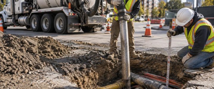
Vacuum excavation is commonly used for utility crossing verification because it removes soil with air or water and a high-powered vacuum rather than relying on a bucket directly around a known or suspected utility. It is a practical way to daylight underground utilities, observe their configuration, and measure conditions at a specific conflict point.
Why utility crossings create design and construction risk
A crossing shown on a composite utility plan may look clear at first glance. In the field, however, the utilities may be closer together than expected, shifted from their mapped alignment, installed at a different depth, or routed through a casing or duct bank. Those differences can affect whether a proposed pipe, structure, footing, trench, or horizontal directional drill (HDD) installation can proceed as designed.
Records can differ from field conditions for many reasons:
- Original installation may have varied from the design or record drawing.
- Older records may show an approximate route rather than a surveyed location.
- Later repairs, relocations, or abandonment work may not be fully documented.
- Street reconstruction, grading changes, and settlement can change the relationship between a utility and finished grade.
- Several facilities may share a corridor, creating signal distortion or uncertainty during geophysical locating.
These issues do not mean utility records or locating results lack value. They are essential inputs for planning. They do mean that critical crossings should not automatically be treated as verified just because lines intersect on a plan.
Locating a utility is not the same as verifying a crossing
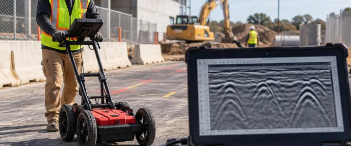
Utility locating and utility verification serve different purposes. A qualified utility locator may use EM methods, GPR, records research, site observations, and other methods to designate the likely horizontal position of utilities. This work is valuable for identifying hazards and targeting further investigation.
Yet a designation is an interpreted result. An estimated depth from an EM receiver can be influenced by field conditions, signal coupling, congestion, soil conditions, and the way the facility carries or responds to a signal. GPR results also require interpretation and may be limited by soil conductivity, moisture, depth, reinforcing steel, and other subsurface features.
Physical utility exposure allows the team to observe what is actually present at the test-hole location. Depending on access and the extent of exposure, this may include:
- The actual horizontal position of each exposed facility.
- Depth below the existing surface at the exposure point.
- The vertical relationship between crossing utilities.
- Pipe outside diameter or visible conduit dimensions.
- Material that can be observed, such as ductile iron, steel, PVC, HDPE, concrete, or conduit.
- Multiple conduits, duct-bank arrangement, casings, protective coverings, or appurtenances.
- Evidence that an expected facility is absent from the specific investigation area.
Physical exposure still has limits. A single pothole verifies conditions at that location, not necessarily along the entire alignment. The visible exterior of a facility may not establish its ownership, service status, internal condition, or exact route beyond the exposed area. The work plan should match the decision the project team needs to make.
How vacuum excavation supports utility crossing verification
A utility crossing investigation should begin with a question that is specific enough to guide the test-hole location. For example: Does the proposed storm sewer pass above or below the existing gas main? Is there enough vertical clearance between a communications duct bank and a proposed water line? Can an HDD bore maintain its planned separation from an existing sewer crossing?
A practical crossing-verification workflow
- Review available information. Compare utility records, civil plans, survey data, prior SUE deliverables, and planned excavation or installation limits. Identify where a crossing could affect design or field work.
- Designate likely utility routes. EM locating, GPR, visual evidence, and record research can help establish the suspected horizontal position and select a targeted test-hole area. Visionary Subsurface Solutions can support this early work through Subsurface Utility Engineering and QL-B services.
- Select exposure points deliberately. The test hole should be positioned to expose the relevant facilities safely and obtain the information the design or construction team needs. One point may not expose both utilities if they converge gradually or their routes are uncertain.
- Excavate using an appropriate method. Hydro excavation uses pressurized water to loosen soil for vacuum removal. Air excavation uses compressed air. The appropriate method depends on soil, site access, restoration needs, water management, utility sensitivity, and project requirements.
- Expose and observe carefully. Crews should use suitable techniques, equipment settings, and hand tools as conditions require. Vacuum excavation reduces the need for mechanical digging near utilities, but it is not risk-free. Qualified operators, utility information, safe work practices, and jobsite controls remain necessary.
- Measure and document the result. Record measurements from a defined reference, note the exposed facility characteristics, take project-appropriate photographs, and identify the point relative to project control. If design requires reliable coordinates or elevations, involve a surveyor or use approved survey procedures.
- Use the findings to resolve the conflict. The engineer, contractor, and utility stakeholders can then assess clearance, adjust the design, revise installation sequencing, or investigate further if the exposure does not answer the question.
Depth measurement versus surveyed elevation
These terms are related but should not be used interchangeably. Confusing them can create avoidable problems in design profiles and construction layouts.
- Estimated depth: A geophysical locating method may provide an estimated depth, often referenced from the receiver position to the detected signal. It is useful for planning but should be understood as an estimate.
- Measured depth after exposure: Once a utility is daylighted, the distance from a defined surface reference to the top, centerline, or invert of the utility can be physically measured. The report should clearly state the reference point and what part of the facility was measured.
- Surveyed elevation: A survey ties the observed utility point to a project datum and control network. This may be necessary when the design depends on precise plan-and-profile information, vertical clearance, or coordinated construction staking.
A vacuum excavation contractor can expose the facility so it can be measured. Vacuum excavation alone does not automatically create a surveyed elevation. The project team should define whether field measurements are sufficient or whether survey-grade horizontal and vertical coordinates are required.
Where Quality Level A fits into a crossing investigation
In Subsurface Utility Engineering, ASCE 38-22 describes Quality Level B as information obtained through the application of appropriate surface geophysical methods to designate the horizontal position of subsurface utilities. Quality Level A is the highest level of accuracy and involves exposing a utility and obtaining precise horizontal and vertical position data, along with other relevant characteristics, at a point.
Vacuum excavation is often an effective method for facilitating physical exposure used in a Quality Level A investigation. However, not every utility pothole automatically provides Quality Level A information. The investigation must be planned, performed, measured, and documented to meet the project’s defined requirements. The American Society of Civil Engineers’ ASCE 38-22 standard overview and Federal Highway Administration guidance on Subsurface Utility Engineering provide helpful context on the role of utility investigation in project development.
For a critical crossing, the value is not simply the label. It is having reliable, documented information that allows the design and construction teams to address a conflict before an excavator, drill rig, or installation crew reaches it.
When engineers should specify utility test holes at crossings
Test holes are most useful when the result will change a decision. Engineers and project managers should consider utility potholing services when a crossing affects:
- A proposed gravity sewer or storm line with limited slope flexibility.
- A water main, force main, or other pressurized utility that needs defined clearance.
- Footings, retaining walls, drilled shafts, light-pole bases, or other structures.
- An HDD entry, exit, or proposed bore path.
- A roadway project with extensive existing utility congestion.
- A utility relocation, tie-in, casing installation, or connection point.
- A suspected conflict between public and private utilities on a commercial site.
- A construction sequence where unexpected conditions could shut down a planned excavation.
Early test holes can allow time to adjust a profile or alignment before documents are finalized. During construction, targeted daylighting can clarify field conditions before crews begin work near a known facility. In either case, the best approach is a planned investigation tied to actual design and construction decisions—not random holes across the site.
Hydro excavation or air excavation for a utility crossing?
Both methods are forms of non-destructive excavation, and neither is automatically right for every utility crossing.
Hydro excavation uses water to break up soil so the vacuum system can remove it. It can be productive in many soil types, but it creates slurry that must be managed and disposed of according to site-specific requirements. Water use, freezing conditions, restoration constraints, and utility-owner requirements can also affect suitability.
Air excavation uses compressed air to loosen soil for removal. It may reduce water and slurry handling and can be useful where dry spoils are preferred. Production can vary significantly with soil type, moisture, compaction, cobbles, and frozen ground.
Access, traffic control, vacuum-truck staging, groundwater, work-zone size, depth, soil conditions, restoration requirements, and disposal planning should all be addressed before work begins. In congested corridors, crews may also need to expose utilities in stages rather than opening a larger area than necessary.
Common mistakes that leave crossing questions unanswered
- Testing beside the actual conflict point. An exposure that is too far from the anticipated crossing may not establish the needed vertical relationship.
- Measuring without a clear reference. A depth number is less useful if it does not identify whether it is to top of pipe, centerline, invert, finished grade, or another reference.
- Assuming the exposed pipe is the only utility present. Conduits, abandoned lines, duct banks, and parallel facilities may be nearby.
- Failing to tie results to project control. If the information will drive design, a clear location reference and survey coordination may be needed.
- Treating one pothole as proof of an entire route. Conditions can change away from the exposure point.
- Waiting until the work is underway. Late discovery may leave fewer options for resolving a conflict safely and efficiently.
Make utility crossing information usable in the field
After exposure, findings should be shared in a form the project team can use. At a minimum, this commonly includes the test-hole identifier, location reference, exposed utility description, measurement reference, observed depths or elevations, dimensions observed, photographs where appropriate, and notes on any discrepancy from available plans.
When a crossing remains uncertain, the finding should be stated plainly. A limited exposure may show one facility but not fully reveal the second. Additional test holes, survey, pipe inspection, or coordination with the utility owner may be appropriate depending on the risk and the decision at hand.
Plan utility crossing verification before it becomes an emergency
Vacuum excavation gives engineers and contractors a controlled way to observe real subsurface conditions where the consequences of uncertainty are highest. It can help confirm whether a utility conflict is real, quantify the vertical separation that matters to the work, and support safer decisions around excavation, drilling, and installation.
For projects in Pennsylvania, New Jersey, Delaware, Maryland, New York, or the Washington, D.C. to New York City corridor, contact Visionary Subsurface Solutions to discuss targeted vacuum excavation and QL-A utility verification for critical utility crossings.