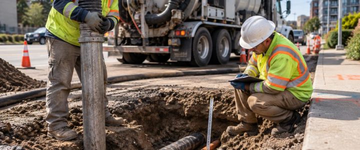
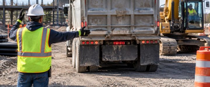
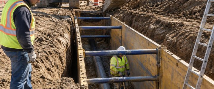
Utility test holes are most valuable when they answer a specific design or construction question. Rather than daylighting every marked line across a site, a well-planned test-hole program focuses on the utilities that could control a proposed grade, trench, structure, bore path, or excavation method.
For civil engineers, surveyors, and contractors, the central question is not simply, “Where are the utilities?” It is, “Which underground conditions must be physically verified before we can make a reliable decision?” Vacuum excavation provides a controlled way to expose those utilities so their actual position and observable characteristics can be measured and documented.
This matters because records, as-builts, utility maps, and surface marks are useful starting points, not guarantees of field conditions. A line may be offset from the plan location, installed at a different depth, rerouted during a prior project, or affected by later grading and reconstruction. Locating methods can help designate a probable path, but physical exposure may be necessary when design or excavation depends on reliable horizontal and vertical information.
Start with the decision the test hole must support
The best utility potholing plan begins with the proposed work, not with a random grid of holes. Review the current design, available records, existing utility designation, proposed grades, and construction limits. Then identify where unknown utility information could change the project.
Common design and construction decisions that justify utility test holes include:
- Setting the profile of a proposed storm, sanitary, water, or force main.
- Confirming whether an existing utility conflicts with a proposed structure, footing, retaining wall, or drainage system.
- Determining vertical separation at an apparent utility crossing.
- Confirming clearance for a utility relocation, casing, or new service connection.
- Verifying a route before directional drilling, trenching, or saw cutting.
- Checking the depth of a utility that falls within an excavation or grading area.
- Confirming the size, material, or configuration of a line before designing a connection or relocation.
- Investigating conflicting information among plans, records, field marks, and visible appurtenances.
Each hole should have a stated purpose. For example: “Verify top elevation, outside diameter, and horizontal position of the indicated gas main at proposed storm crossing.” That purpose helps the field team select the right exposure point and helps the project team know what to record.
Use utility designation to target physical verification
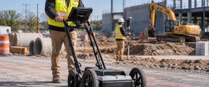
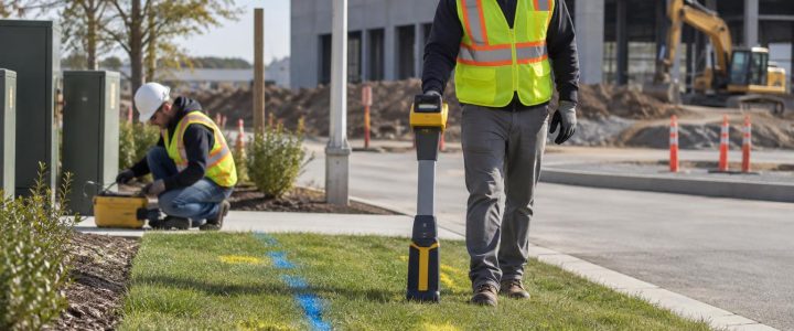
Utility locating and utility verification are related, but they are not the same task. Electromagnetic locating can trace many conductive utilities from a known access point. Ground penetrating radar can sometimes identify subsurface features and help investigate areas where direct tracing is limited. Both methods can support utility designation, but their results are interpreted from the surface and have practical limits.
A test hole is used to physically expose the utility. Once exposed, the team can observe the actual utility rather than relying only on a surface indication or estimated depth reading. This is particularly important where the consequence of being wrong is high.
Within the Subsurface Utility Engineering framework, Quality Level B generally involves geophysical designation of utilities, while Quality Level A involves physical exposure and measurement at discrete points. The Federal Highway Administration’s SUE guidance and ASCE utility investigation standards information describe why the quality of utility information should match the decisions being made. A vacuum excavation project does not automatically satisfy every Quality Level A requirement. The exposure location, measurement methods, survey control, documentation, and project scope all matter.
For projects that need a coordinated investigation before excavation, Visionary Subsurface Solutions can combine Subsurface Utility Engineering and QL-B designation with targeted test holes. This sequence helps concentrate physical verification at the locations that matter most.
Where should utility test holes be placed?
Test-hole locations should be selected at points where the proposed work and the utility system create the greatest uncertainty or risk. The following locations are often high priorities.
Proposed utility crossings
When a proposed pipe, duct bank, conduit bank, or bore crosses an existing utility, the key unknown is often vertical separation. A surface locate may indicate an apparent crossing, but it may not establish which line is above the other or whether there is adequate clearance for construction.
Expose the existing utility at or near the planned crossing point when practical. Depending on the project, one test hole may be enough, or additional holes may be needed on either side to understand the line’s direction, grade, bends, or changing depth. Do not assume a utility maintains a constant elevation between distant points.
Profile control points
For gravity systems and other grade-sensitive work, the existing utility elevation can control the proposed design. Test holes are commonly placed where a proposed line approaches an existing crossing, where a proposed low point is planned, or where available utility information leaves little room for adjustment.
Physical exposure can provide a measured depth below the existing surface. If the design requires a precise elevation, the exposed utility should be tied to suitable survey control using appropriate survey procedures. A measured depth alone is not automatically a surveyed elevation, especially where pavement thickness, future grading, or varying surface conditions affect the reference point.
Conflict areas near structures and excavation limits
Test holes are useful near proposed building additions, foundations, retaining walls, light pole bases, sign foundations, inlet structures, and deep landscape features. A utility may be outside the apparent footprint but still fall within the excavation slope, shoring zone, equipment working area, or required clearance area.
Consider both the proposed structure and the means of construction. The utility that is clear of a finished foundation may still conflict with a temporary trench, soldier pile, dewatering system, or haul route.
Changes in alignment or suspected utility bends
Utilities do not always run in straight lines. Direction changes are common near valves, manholes, buildings, service connections, previous repairs, and congested corridors. If a designated line changes direction near proposed work, a test hole at the suspected bend can provide more useful information than a hole at a convenient straight segment.
Points where records disagree
Conflicting records are a strong reason to investigate, not a reason to select the preferred drawing. Compare utility owner records, civil base mapping, record drawings, visible structures, private utility locating results, and previous investigation data. When they do not agree, prioritize the discrepancy that could affect the design or excavation.
What a properly planned test hole can verify
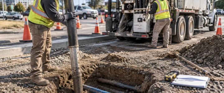
When conditions allow safe exposure, vacuum excavation for utilities can reveal information that cannot reliably be confirmed from electromagnetic locating or GPR alone. Depending on the extent of exposure and the utility condition, observable information may include:
- Actual horizontal position at the exposure point.
- Depth measured from the existing ground or pavement surface to the exposed utility.
- Surveyed horizontal and vertical coordinates when the exposed utility is tied to survey control.
- Outside diameter or observable size of a pipe, conduit, cable bundle, or casing.
- Material that can be visually identified, such as ductile iron, steel, PVC, HDPE, concrete, or other observable materials.
- Number and arrangement of conduits in an exposed bank.
- Casing, encasement, tracer wire, warning tape, abandoned lines, or nearby parallel facilities.
- Observable configuration at a crossing, including which exposed utility is above or below another.
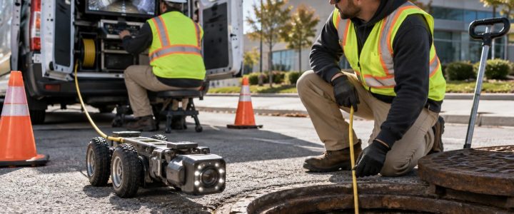
Exposure has limits. A small pothole may not reveal the full configuration of a congested duct bank, the condition of a utility beyond the opening, or the ownership of a line. Ownership should be confirmed through records and coordination with the appropriate utility owner or facility representative. If pipe condition is the concern, additional methods such as video pipe inspection may be more appropriate than a test hole alone.
Plan the test-hole scope before mobilization
Test holes are more efficient when the project team agrees on the questions, locations, access requirements, and deliverables before field work begins. A practical scope should address the following items.
- Utility targets: Identify the specific lines, structures, or crossings to be investigated and explain why each is important.
- Expected location: Provide current plans, records, and designated utility markings so the crew can work from the best available information.
- Required information: State whether the project needs only utility exposure, measured depth, dimensions, photographs, survey coordinates, elevations, or a formal test-hole record.
- Surface and access conditions: Note pavement, landscaping, traffic, secure facilities, railroad areas, restricted work hours, and equipment access limits.
- Restoration expectations: Define how pavement, concrete, turf, aggregate, and other disturbed surfaces should be restored.
- Material handling: Address soil, water, slurry, and disposal requirements based on site conditions and applicable project procedures.
On complex sites, it is often wise to complete the highest-priority holes first, review the findings, and then decide whether more verification is needed. One exposure can change the utility conflict picture and prevent unnecessary holes elsewhere.
Choose hydro or air excavation based on the job
Hydro excavation uses pressurized water to loosen soil while a vacuum system removes the spoil. It can be productive in many soil types and is commonly used for utility daylighting. It also creates slurry that must be managed and disposed of appropriately.
Air excavation uses compressed air to loosen soil for vacuum removal. It may be useful where dry spoil handling, reduced water use, or restoration concerns are important. However, soil type, compacted material, rock, groundwater, frozen ground, and production requirements can affect performance.
Neither method is universally better. The right non-destructive excavation method depends on the utility, soil, required hole size and depth, access, weather, nearby sensitive infrastructure, and the project’s restoration and material-management needs. Both methods require careful operation around known or suspected utilities. Vacuum excavation is intended to reduce the risk associated with mechanical digging near utilities; it does not eliminate risk.
Common mistakes that weaken a utility verification effort
- Testing only convenient locations: A hole that is easy to access may not answer the controlling design question.
- Relying on a single estimated depth: Surface-based depth estimates should not be treated as final design elevation data without verification.
- Failing to establish survey needs in advance: If a surveyed elevation is needed, involve the survey team and control requirements before the hole is backfilled.
- Not documenting the reference surface: Record whether depth was measured from pavement, finished grade, existing grade, or another defined reference.
- Assuming one exposed line tells the whole story: Nearby parallel utilities, crossings, and abandoned infrastructure may require a wider or separate investigation.
- Waiting until excavation starts: Late discovery can force redesign, field changes, work stoppages, and hurried decisions.
Turn exposure findings into usable project information
The value of utility daylighting is not the hole itself. It is the documented information used by the design and construction team. After each exposure, compare the finding with the plans and prior designations. Update the utility conflict matrix, plan profile, utility map, construction sequence, or bore plan as needed.
Include the limitations of the finding as well. A utility was verified at a specific point and date; that does not prove its alignment, depth, or condition across the entire site. Clear records help future users understand both what was observed and what remains uncertain.
For projects across Pennsylvania, New Jersey, Delaware, Maryland, New York, and the Washington, D.C. to New York City corridor, Visionary Subsurface Solutions provides vacuum excavation and QL-A utility exposure services to support targeted utility verification. Contact our team to discuss the utility questions, access conditions, and documentation needs for your project.