Electromagnetic utility locating is often the fastest way to trace a conductive underground line before construction, excavation, or design work. But an EM receiver does not simply “see” every utility below ground. It follows an electromagnetic field created by current on a conductor. The quality of that signal—and the confidence a contractor can place in the resulting marks—depends heavily on how the signal is applied and what frequency is used.
For contractors and engineers, the practical question is not just whether a line can be located. It is whether the line can be traced reliably enough to plan work, avoid conflicts, or decide where physical verification is needed. A professional private utility locator evaluates access, conductor type, grounding, congestion, and interference before selecting a locating method.
In many cases, lower frequencies with a direct connection provide the cleanest trace. In others, a clamp or induction is the only workable option. Each method has tradeoffs that affect signal strength, distortion, and the chance of unintentionally following a neighboring utility.
How electromagnetic utility locating works
An EM locating system generally includes a transmitter and a receiver. The transmitter applies a selected frequency to a conductive target, such as a metallic pipe, cable, conduit, or tracer wire. The receiver detects the resulting electromagnetic field at the surface and helps the locator follow the apparent path of that conductor.
The process can support three related, but different, field tasks:
- Detection: determining whether a detectable signal is present in an area.
- Tracing: following that signal to mark the apparent horizontal route of a utility.
- Depth estimation: calculating an estimated depth from the detected field, subject to favorable field conditions.
These are not the same as proving utility ownership, material, status, or exact position. A marked line represents an interpreted surface indication of a detected signal. When excavation will approach a marked utility, a vacuum-excavated test hole may be needed to establish its actual horizontal and vertical location.
Active and passive EM locating
Active locating means the locator intentionally applies a transmitter signal to a target conductor. This is usually the preferred approach when there is an accessible point of connection, such as a cable pedestal, valve box, meter, tracer wire termination, utility cabinet, or exposed conductor.
Passive locating uses signals already present on a line. A receiver may detect power-frequency current on energized electrical facilities or radio-frequency energy that has coupled onto long conductive utilities. Passive sweeps can be useful during an initial utility investigation, but a passive response alone may not provide a unique or continuous trace. It can also respond to current on more than one conductor.
For utility locating before excavation, active tracing is often more useful because the locator can control the applied frequency and test whether a trace behaves consistently from point to point. Passive locating remains a valuable supplemental check, especially around electrical infrastructure and where access for a transmitter connection is limited.
Three ways to apply an active locating signal
Direct connection: the preferred method when access is available
With direct connection, the transmitter lead is connected to the target conductor and the transmitter ground lead is placed on a suitable ground point. This establishes a circuit that places signal current onto the intended line.
Direct connection often allows use of a lower frequency, which can help keep the signal concentrated on the target. It is especially useful for accessible metallic pipes, bonded cable sheaths, abandoned metallic lines with accessible ends, and tracer wires that are continuous and reachable.
However, direct connection is not automatically clean. Signal can transfer through bonds, shared grounds, metallic crossings, cable shields, or other conductive paths. A locator should observe signal behavior and check nearby parallel lines rather than assume the connected facility is the only one carrying the signal.
Inductive clamp: useful for accessible cables and wires
An inductive clamp is placed around a cable, conduit, or tracer wire. The clamp induces a transmitter signal onto the enclosed conductor without a direct metal-to-metal connection. This can be helpful where a direct connection is impractical or undesirable, including certain energized cable applications when appropriate procedures and equipment are used.
The clamp must surround the intended conductor completely. If several conductors are within the clamp, or if the clamped conductor is bonded to other facilities, the receiver may still detect signal on multiple paths. The method is practical, but the trace should be checked carefully where the route enters congested areas.
Induction: a valuable option with greater risk of coupling
Induction places the transmitter on the ground or near an accessible utility feature to radiate a signal into nearby conductors. It is useful when no direct connection or clamp point is available. For example, induction may help investigate an unknown metallic line near a valve box, a corridor with no exposed cable, or a site where access is restricted.
The limitation is selectivity. The transmitter can energize more than the intended facility, particularly in dense corridors. The receiver may respond to several metallic lines, fences, reinforced structures, aboveground steel, or nearby conductors. A professional locator normally starts the receiver some distance from the transmitter when practical and uses field checks to separate likely target signals from broad induced responses.
Why frequency selection matters
There is no single “best” EM locating frequency. A useful frequency is one that puts enough detectable signal on the target while minimizing transfer to other conductors. The lowest practical frequency is often a sound starting point for a direct connection because it may be less prone to traveling onto adjacent utilities.
Higher frequencies can be helpful when the target has poor continuity, weak grounding, insulation, a long route, or a damaged tracer wire. They may also be necessary when a lower-frequency signal is too weak to follow. The tradeoff is that higher frequencies generally have a greater tendency to couple or bleed onto nearby conductive paths.
A professional EM utility locator may test more than one frequency and compare the response. The goal is not to find the strongest signal alone. It is to find a signal that produces a stable, believable trace that remains consistent with access points, visible appurtenances, available records, and other field evidence.
Practical frequency-selection questions
- Is there a safe, accessible point for direct connection?
- Does the target have a continuous metallic path or an intact tracer wire?
- Are several utilities running in parallel or crossing nearby?
- Is the route near buildings, fencing, substations, rail infrastructure, or industrial equipment?
- Does the signal remain centered and consistent as the route is traced?
- Does changing frequency produce a different apparent route or depth estimate?
A change in response does not automatically mean one result is wrong. It is a reason to investigate further and document uncertainty before excavation proceeds.
Depth readings are estimates, not physical verification
EM receivers can estimate depth by measuring characteristics of the detected field. The estimate is most meaningful when the receiver is centered over a single, undistorted signal and the line is reasonably straight beneath the receiver. It should not be treated as an exact buried elevation.
Depth estimates can be affected by a wide range of site conditions, including:
- Signal coupling onto adjacent or parallel utilities.
- Multiple conductors carrying the same applied signal.
- Changes in utility direction, bends, tees, offsets, or coiled slack.
- Nearby reinforced concrete, structural steel, guardrails, fences, and other metal.
- Weak signal current, damaged tracer wire, poor grounding, or discontinuous pipe sections.
- Receiver position that is not directly over the target signal.
- Deep lines and congested utility corridors.
A stable estimated depth can assist with planning, but it does not replace daylighting where an excavation, bore path, footing, or crossing must be cleared. Vacuum Excavation & QL-A provides a non-destructive way to expose a utility and document the observed location and attributes at a specific point.
What EM equipment can and cannot typically locate
EM equipment is designed to trace conductive utilities or a conductive component associated with a utility. Common examples include metallic water, gas, and fire lines; steel conduit; copper cable; metallic communication cable components; and accessible tracer wires installed alongside non-metallic pipe.
Plastic, PVC, HDPE, fiberglass, concrete, and other non-conductive utilities generally cannot be directly traced with EM equipment. They may be locatable if they contain a continuous tracer wire, detectable metallic tape, a metallic component, or another conductive path that can carry a signal. The presence of a signal on a tracer wire helps trace the wire; it does not by itself prove the pipe is directly below it at every point.
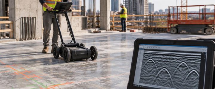
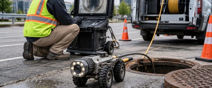
Non-metallic lines without a usable tracer wire may require another investigation method. Ground penetrating radar can be considered where site conditions are suitable, though it also has limitations related to soil, moisture, depth, clutter, and utility size. For accessible sewer or storm structures, camera inspection and sonde locating may help trace a particular pipe route. The appropriate method depends on the utility type and the construction decision that must be made.
Why congested corridors create difficult EM locates
In utility-dense areas, several lines may run parallel within a narrow trench zone. A signal applied to one conductor can couple to adjacent lines. The receiver can then detect a blended field rather than a single, isolated target. This may cause the apparent position to wander, shift as the locator changes frequency, or appear between two actual facilities.
Complex sites create similar challenges. Buildings may contain extensive grounding and structural steel. Substations and industrial facilities may produce electrical interference. Roadways can include signal loops, lighting circuits, guardrails, and reinforced features. Abandoned utilities may remain connected to active systems or may be disconnected in ways that prevent a usable trace.
Good field practice includes tracing from more than one access point when possible, checking for signal on adjacent lines, changing frequencies deliberately, investigating route changes, and correlating results with visible features and records. It also includes reporting areas where the signal is ambiguous instead of presenting an uncertain result as confirmed fact.
How EM locating supports Quality Level B utility designation
Under ASCE 38-22, Quality Level B utility information is developed through the application of appropriate surface geophysical methods to designate the approximate horizontal position of subsurface utilities. Electromagnetic utility locating is one of the methods that may contribute to Quality Level B work when it is suitable for the utility and site conditions.
An EM locate alone does not automatically create a complete SUE deliverable. Quality Level B work involves a planned investigation, appropriate records research and field methods, documented designations, and professional judgment about the quality and limitations of the information. Learn more about Subsurface Utility Engineering & QL-B when design decisions require a broader utility investigation.
When to bring in private utility locating services
Public 811 locates are an important first step, but they commonly address member utility facilities within the public notification system. Privately owned utilities beyond the meter, building services, campus systems, site lighting, private electric, fire protection, and owner-installed communications may not be included. Scope varies by facility and utility operator, so contractors should review the response and markings rather than assume the entire site has been cleared.
Private utility locating is especially useful before trenching, directional drilling, pavement coring, utility installation, demolition, stormwater work, foundation excavation, or work on commercial and industrial properties. Bring in a utility locating company early when plans are incomplete, the property has changed over time, or the consequence of a strike is high.
Field checklist before an EM utility locate
- Complete the 811 notification process early enough for the required response window.
- Define the excavation limits, bore path, proposed structures, and access constraints.
- Provide available civil plans, utility sketches, as-builts, and prior test-hole information.
- Identify locked rooms, electrical rooms, meter locations, valve boxes, manholes, and other potential connection points.
- Clear vehicles, stored material, and debris where practical so markings can be placed and traced.
- Discuss private systems, recent renovations, abandoned services, and known utility issues with the locator.
- Plan physical verification at critical crossings, tie-ins, and areas within the excavation influence zone.
FAQ: electromagnetic utility locating for construction
Can EM locating find a PVC water or sewer line?
Not directly in most cases. It may trace an installed tracer wire or metallic component associated with the pipe. Without a usable conductive path, another method may be needed, and results remain dependent on site conditions.
Does a strong EM signal prove the exact location of a utility?
No. A strong signal can still be coupled to nearby conductors or distorted by congestion. The signal should be interpreted through field checks, and critical locations should be physically verified before intrusive work.
Should a contractor rely on an EM depth reading to set excavation depth?
No. Use the reading as planning information, not as physical confirmation. Where clearance matters, use appropriate safe excavation practices and daylight the utility as needed.
Plan the locate around the construction decision
The best electromagnetic utility locating approach starts with the decision the field team needs to make: where to trench, where to bore, whether a crossing is viable, or where to place a structure. That decision guides the appropriate signal application method, frequency testing, supplemental technology, and test-hole plan.
Visionary Subsurface Solutions provides private utility locating and EM utility investigation services throughout Pennsylvania, New Jersey, Delaware, Maryland, New York, and the Washington, D.C. to New York City corridor. Contact our team to discuss the utility risks, access conditions, and verification needs for your project before excavation begins.