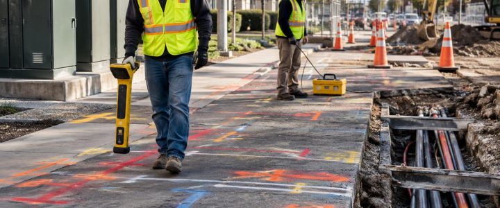
Before trenching, boring, drilling, or setting foundations, project teams need more than a paint mark. They need to understand what the mark represents, how the utility was traced, and where uncertainty remains. Electromagnetic (EM) utility locating is one of the most useful methods for tracing conductive underground lines, but the quality of the result depends heavily on the way a signal is applied and the frequency selected.
For contractors and engineers, the practical question is not simply, “Can this line be located?” It is, “Can we place a usable signal on this specific utility, follow it without confusing it with adjacent lines, and verify the result to the level required for the work?” A professional private utility locator evaluates those questions in the field rather than relying on one locating method or one frequency.
How electromagnetic utility locating works
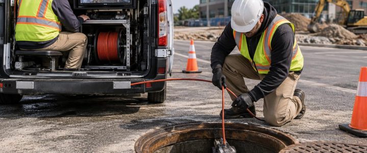
EM utility locating equipment consists primarily of a transmitter and a receiver. The transmitter applies an electromagnetic signal to a conductive target, such as a metallic pipe, cable, conduit, or tracer wire. The receiver is then used at the ground surface to detect the signal field and trace the apparent route of that target.
The equipment does not “see” the pipe or cable in the same way a camera sees an object. It detects a signal field. That distinction matters because the field can be affected by nearby conductors, changes in grounding, bends, tees, poor connections, soil conditions, and electrical interference.
EM locating is commonly effective for:
- Metallic electrical, communications, and control cables
- Steel, iron, copper, and other conductive pipes
- Metallic conduit
- Non-metallic pipe with an accessible, continuous tracer wire
- Some detectable tapes, sonde transmitters, and metallic components when they can carry or emit a usable signal
Plastic, PVC, HDPE, fiberglass, concrete, and other non-conductive utilities generally cannot be directly traced with an EM receiver unless a conductive tracer wire, metallic component, detectable tape, or inserted transmitter provides a signal path. A plastic pipe with a broken, disconnected, or inaccessible tracer wire may require another investigation method.
Three ways to apply an EM locating signal
The signal application method is often as important as the receiver settings. A locator should select the method that creates the clearest, most controllable signal on the intended utility while limiting signal transfer to other lines.
Direct connection
Direct connection places a transmitter lead directly onto an accessible conductive facility or tracer wire. The other lead is connected to an appropriate ground point according to the equipment procedure and field conditions. Common access points include utility pedestals, valve boxes, meter connections, handholes, exposed conduit, cleanouts with tracer wire access, and cable ends.
When it can be performed safely and properly, direct connection often provides the most controlled way to trace a specific target. It is particularly useful when a corridor contains several parallel utilities and the team needs to distinguish one line from another.
Direct connection still has limitations. A damaged conductor, coating, insulating joint, disconnected tracer wire, poor ground return, or long branch network can weaken or alter the signal. The signal may also transfer onto nearby bonded or parallel utilities. A clear trace near the connection point does not automatically prove that the same signal remains isolated farther along the route.
Direct connection should only be performed by qualified personnel using the manufacturer’s procedures and site-specific safety controls. A locator should not make an unapproved connection to energized electrical equipment or interfere with utility system components.
Inductive clamp application
An inductive clamp applies a signal by clamping around an accessible cable, pipe, or tracer wire. It is useful when there is access to a single conductor but direct electrical contact is not practical or appropriate.
For example, a clamp may be used around an accessible cable at a pedestal or around a tracer wire where it can be separated from other conductors. The method depends on the target forming a usable circuit. If the clamp surrounds multiple conductors, the resulting signal may be difficult to interpret because more than one line may be energized.
Clamp application can be a good middle ground between direct connection and induction. It avoids physical electrical contact with the target, but it still requires enough access and separation to place the clamp around the intended line only.
Induction
With induction, the transmitter is placed on or near the ground and broadcasts a signal into nearby buried conductors. This is useful when there is no safe or practical access point for a direct connection or clamp.
Induction is often valuable for an initial search, but it requires careful interpretation. The transmitter can energize multiple nearby metallic lines, especially in a congested utility corridor. The receiver may respond strongly to a nearby line that is not the line the crew expects to find. Induction works best when the locate area can be managed to reduce nearby interference and when the locator verifies the trace from multiple positions.
Choosing an EM locating frequency
There is no single “best” locating frequency for every underground utility. Frequency selection is a field decision based on the target, access, grounding, congestion, and distance to be traced.
In general, lower frequencies tend to stay on the intended conductor more effectively when a solid direct connection and good return path are available. This can help reduce unwanted coupling onto nearby lines. Higher frequencies can be useful when the signal is weak, the line is poorly grounded, the target is difficult to energize, or the utility must be traced over a challenging route. However, higher frequencies are also more likely to couple or bleed onto adjacent conductors.
A practical locating workflow often starts with the lowest frequency that produces a reliable trace, then changes frequency only when field conditions justify it. The locator should watch for changes in signal response rather than assuming a stronger signal is always a better signal.
Common signs that frequency or application method may need to change include:
- The signal drops off unexpectedly along a route
- Several parallel lines respond at similar strength
- The apparent route shifts when the receiver gain changes
- The signal becomes broad, inconsistent, or difficult to peak
- The trace follows a route that conflicts with known access points or visible utility features
- A signal appears on a line that should not be connected to the target
Why congested corridors create difficult EM locates
Commercial sites, roadways, industrial facilities, campuses, and older urban properties frequently have utilities installed close together. Parallel electric, communications, gas, water, sewer, irrigation, and abandoned lines can create overlapping fields and confusing receiver responses.
Signal coupling is a common concern. A signal intentionally applied to one conductor can transfer to another nearby conductive path through direct bonding, shared grounding, capacitive coupling, or inductive coupling. This can make two utilities appear to follow the same route, even when they separate farther ahead.
Field teams manage this risk by comparing responses at different frequencies, checking the trace from more than one direction, reviewing visible features, and looking for signal changes at branches, bends, crossings, and access structures. When the consequences of a wrong assumption are high, a mark should be treated as an investigation result, not final proof of the utility’s exact location.
Passive locating: useful, but not a complete utility search
Passive EM locating does not use a transmitter. Instead, the receiver listens for signals already present on a buried conductor, such as power-frequency current or re-radiated radio-frequency energy.
Passive sweeps can help identify some energized electrical lines and conductive utilities carrying ambient signals. They are useful as part of a broader search before active tracing begins. However, a passive response does not identify every underground utility, and no passive response proves that an area is clear.
A de-energized cable, an electrically isolated pipe, a plastic utility, or a metallic utility with little usable ambient signal may not be found by passive methods. Passive signals can also be present on a line that is not the utility of concern. For excavation planning, passive locating should support—not replace—active EM tracing and other appropriate investigation methods.
What an EM depth reading means
Many EM receivers can calculate an estimated depth after the operator has centered the receiver over a stable, identifiable signal. The estimate is based on the geometry and strength of the detected field. It is not a direct measurement of the top, center, or bottom of the physical utility in every situation.
Depth estimates can be affected by distorted fields, parallel utilities, multiple conductors, utility bends, tees, changes in current flow, signal coupling, poor centering, and the target’s orientation. A deep apparent reading may reflect a distorted field, while a shallow reading may reflect a nearby coupled conductor rather than the intended target.
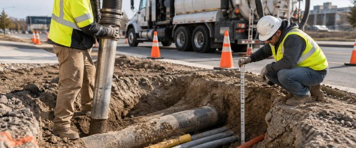
For this reason, EM depth information is useful for planning and risk assessment, but it should not be used as the sole basis for excavation clearance, crossing design, or drilling depth. Where vertical position matters, vacuum excavation and test holes can physically expose the utility and document its actual observed location.
EM locating and ASCE 38-22 Quality Level B
ASCE 38-22 describes a Quality Level framework for subsurface utility information. Quality Level B utility designation uses appropriate surface geophysical methods to identify the approximate horizontal position of utilities. EM utility locating is one of the principal methods used for this work when the utility is conductive or can carry a traceable signal.
An EM locate by itself does not automatically create a complete Subsurface Utility Engineering investigation or resolve all utility risks. Quality Level B work requires an appropriate investigation approach, documented field observations, and correlation with available records and surface features. It also does not provide the same level of certainty as Quality Level A, where a utility is exposed and measured at a test hole.
For design projects requiring organized utility designation and documentation, learn more about Subsurface Utility Engineering and Quality Level B services.
When EM locating should be supplemented
EM utility locating is often the starting point for private utility locating, but it may not answer every question on a site. Supplemental methods are appropriate when the target is non-conductive, the site is congested, the route is uncertain, or the consequences of a conflict are significant.
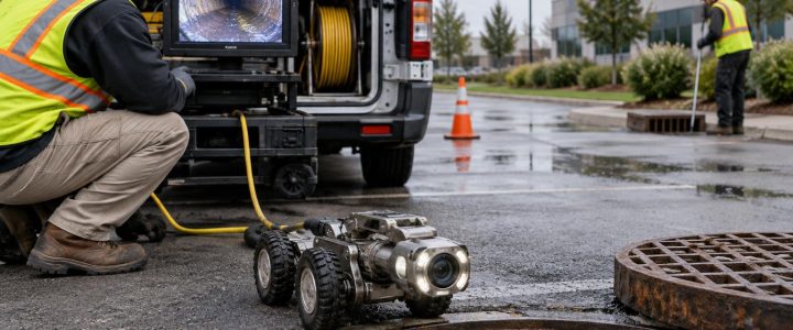
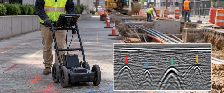
Depending on conditions, the investigation may include ground penetrating radar for certain non-metallic or unknown features, CCTV inspection for accessible pipelines, record review, surface feature correlation, or vacuum excavation. A test hole is especially important before crossing a marked utility with a directional drill, installing deep foundations, excavating near critical services, or finalizing a design elevation.
Pre-locate checklist for contractors and project managers
- Complete the required 811 notification process before excavation and allow time for responses.
- Identify private areas that public utility marks may not cover, including service laterals, campus utilities, site lighting, private electric, irrigation, fire protection, and owner-installed communications.
- Provide available utility plans, as-builts, prior locate reports, survey files, and proposed excavation limits.
- Mark or communicate the planned work area, including staging, bore paths, trench routes, structure locations, and access constraints.
- Make accessible utility features available where practical, such as manholes, handholes, pedestals, valve boxes, cleanouts, and electrical rooms.
- Schedule the locate early enough to investigate unclear results and perform test holes where needed.
- Protect field markings and communicate their meaning to equipment operators and subcontractors.
When to bring in a private utility locating company
Private utility locating is particularly valuable when work extends beyond the scope of public utility markings, when records are incomplete, or when the project has a high cost of disruption. Typical triggers include site redevelopment, utility relocations, building additions, parking lot reconstruction, directional drilling, deep excavation, and work near hospitals, data facilities, industrial plants, schools, and multifamily properties.
A professional utility locating company can select signal application methods, evaluate distorted responses, trace accessible private utilities, document field findings, and recommend where verification is needed. If a marked route or estimated depth is not enough for the planned work, the next step may be a targeted test hole rather than a broader excavation.
Visionary Subsurface Solutions provides private utility locating services for construction and engineering projects across Pennsylvania, New Jersey, Delaware, Maryland, New York, and the Washington, D.C. to New York City corridor. Contact our team to discuss the utilities on your site, the planned work, and the level of investigation that fits your project.