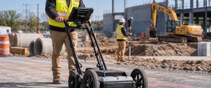
A utility corridor with several buried lines can turn a routine excavation into a high-risk investigation. Electric, communications, gas, water, sewer, irrigation, fire protection, and abandoned facilities may occupy a narrow strip between a roadway, building, curb, or property line. In these areas, one electromagnetic signal can appear to belong to several different lines.
Electromagnetic utility locating can be highly useful for tracing conductive utilities, but it is not a one-pass process in a congested corridor. A professional utility locator must evaluate how a signal was applied, where it travels, how it changes, and whether nearby conductors are carrying some of that signal. Surface marks show an interpreted route based on field evidence. They do not replace careful excavation practices or physical verification where a conflict matters.
This article explains why crowded corridors are difficult, what an EM locator can realistically establish, and how contractors and engineers can plan a more dependable underground utility investigation before excavation.
Why congested utility corridors create difficult locating conditions
EM utility locating equipment detects an electromagnetic field associated with a conductive utility or a conductive path such as a tracer wire. When a signal is deliberately applied to a target line, the receiver is used to trace that signal from the surface.
In an open area with a well-isolated metal pipe or cable, the strongest response may align closely with the target. In a congested corridor, several conditions can make that response less clear:
- Utilities run parallel or cross at shallow angles.
- Multiple lines share a trench, duct bank, rack, or building service route.
- Bonded metallic systems create alternate paths for the applied signal.
- Nearby conductors pick up energy through coupling.
- Signal current leaks to ground through damaged insulation, poor connections, or other paths.
- Reinforced concrete, guardrails, fences, buried metal debris, and street furniture add interference.
- Utility access points are limited by pavement, landscaping, traffic, or active operations.
The challenge is not simply finding a response. It is determining whether the response represents the intended facility, a coupled utility, a branch, or a combination of conductors.
How EM signals can move beyond the intended utility
For active electromagnetic utility locating, a transmitter applies a known frequency to a conductive target. The receiver is then tuned to that frequency. This gives the field team more control than relying only on naturally occurring signals, but it does not force the signal to remain on one utility.
Direct connection usually provides the most controlled signal path
When safe and accessible, a locator can connect the transmitter to an exposed conductive point, such as a cable, tracer wire, valve box component, or metallic pipe. A ground lead completes the circuit. Direct connection often provides a clearer starting point than other methods because the operator knows where the signal entered the system.
Even then, a connected line can transfer signal through bonds, shared neutrals, adjacent conductors, metallic structures, or underground contact points. A strong trace does not by itself prove that the signal stayed on only one facility.
Induction and clamps have practical uses and tradeoffs
An inductive clamp can place a signal on an accessible cable or pipe without making an electrical connection. It can be useful where direct connection is impractical or undesirable. The clamp must fully encircle the target, and the target configuration still affects how the signal travels.
Induction, where a transmitter radiates a signal onto buried conductors, is useful when no access point is available. It is also less selective. Nearby conductive lines may receive the signal, particularly in a tight corridor. A competent field approach treats induction results as evidence to evaluate, not automatic confirmation of one specific utility.
Common signal problems a professional utility locator evaluates
Coupling between parallel utilities
Parallel utilities can act much like adjacent paths that share energy. A signal applied to one metallic line may induce a response on another nearby conductor. The two responses may be difficult to separate at the surface, especially where the facilities are close together or at similar depths.
A locator may compare signal strength, response shape, direction, and changes along the route. The team may also adjust the frequency, alter the transmitter setup, trace from another access point, or isolate a section when conditions allow. These steps help build confidence in the interpretation, but they cannot turn an uncertain corridor into a verified excavation location without additional investigation.
Signal bleed-off and distorted traces
Signal bleed-off occurs when applied current leaves the intended route and follows another path to ground. It may occur at a damaged cable, a poor joint, a bonded component, a branch, or a section where the utility condition changes. A trace that suddenly weakens, widens, shifts, or behaves inconsistently deserves attention.
Distortion can also occur around fittings, valves, risers, manholes, metallic structures, large buried objects, and congested crossings. The apparent peak at the surface may not sit directly over a single target in every condition. This is one reason field markings should be reviewed in context rather than treated as a perfect underground drawing.
Interference from the built environment
Buildings, substations, industrial sites, rail-adjacent areas, roadways, and dense urban properties can introduce additional complexity. Electrical systems, cathodic protection, communication infrastructure, grounded structural steel, fences, and reinforcing steel may influence the locating environment. Limited access may also prevent the locator from walking a full route or testing alternate setups.
When a corridor enters a building or passes near major electrical equipment, a locating plan may need coordination with the facility, safe access to known points, and a clear understanding of the planned excavation limits.
Choosing frequency is about control, not simply range
A common misconception is that the highest available frequency is always the best choice. Higher frequencies can sometimes help establish a signal on a difficult target, but they can also be more likely to couple onto nearby conductors. Lower frequencies may provide a more controlled trace on a well-connected target, yet may not travel effectively across poor joints, insulated sections, or discontinuities.
The appropriate frequency depends on the utility, access point, expected route, grounding conditions, site congestion, and observed signal behavior. In practice, a professional locator may test more than one frequency and compare the results. If a route changes materially between setups, that is useful risk information—not a reason to select the more convenient mark.
What EM locating can and cannot detect
EM equipment is primarily suited to conductive facilities or conductive components that can carry a detectable signal. Examples can include metallic pipe, metallic conduit, copper cable, some steel-cased systems, and tracer wire installed with a non-metallic utility.
Plastic, PVC, HDPE, fiberglass, concrete, and other non-conductive pipes generally cannot be directly traced with electromagnetic equipment alone. A non-metallic line may be traceable if it has a continuous and accessible tracer wire, detectable tape, a metallic component, or another means to apply a signal. The condition and continuity of that component matter. A broken tracer wire or inaccessible termination can limit the result.
EM locating also cannot reliably establish utility ownership, confirm whether a utility is active or abandoned, identify every material change, or guarantee exact depth. Records, visible appurtenances, field observations, and other investigation methods may help interpret a detected line, but each has its own limitations.
Depth estimates are not physical verification
Many EM receivers can calculate an estimated depth based on the detected field and the assumed geometry of the signal. That estimate can be helpful for planning, especially when readings are consistent and the target is reasonably isolated. It should not be treated as the actual exposed depth of a utility.
Depth readings can be affected by signal distortion, adjacent conductors, a signal traveling on more than one path, signal strength, utility orientation, access limitations, and the actual utility configuration. A reading may represent the apparent center of a signal field rather than a confirmed pipe or cable location.
For design-critical crossings, proposed drilling paths, deep excavation, and areas with limited tolerance, vacuum excavation or a test hole is the appropriate next step to physically expose and document the utility. Visionary Subsurface Solutions provides vacuum excavation and Quality Level A services for this purpose.
EM locating and Quality Level B utility designation
Electromagnetic locating is commonly one of the surface geophysical methods used during a Subsurface Utility Engineering investigation. Under ASCE 38-22, Quality Level B information is developed through appropriate surface geophysical methods to determine the approximate horizontal position of subsurface utilities. The work also depends on project scope, field conditions, available records, survey control, documentation, and professional interpretation.
An EM trace alone does not automatically create a complete Quality Level B deliverable. For example, a trace may indicate a conductive path but leave important questions about branches, depth, material transitions, non-conductive segments, or identity unresolved. A coordinated Subsurface Utility Engineering and QL-B investigation can help combine field designation with records research, survey, conflict analysis, and a plan for verification where needed.
A practical workflow before excavating in a crowded corridor
Contractors can reduce uncertainty by treating utility locating as part of preconstruction planning instead of a same-day clearance task.
- Define the work area. Provide excavation limits, bore paths, grading limits, utility tie-in locations, proposed structures, and access constraints.
- Start the public locate process early. Public 811 marks are an important part of the process, but they may not cover privately owned facilities beyond the utility’s responsibility point.
- Identify likely private utilities. Review building services, site lighting, signs, irrigation, fire lines, private communications, parking-lot utilities, and interbuilding connections.
- Share available information. Site plans, utility records, prior marks, as-builts, and known access points can help the locating team select efficient field methods. They should be treated as references, not proof of actual conditions.
- Allow room for investigation. Remove movable obstructions where possible, arrange access to electrical rooms or valve boxes when relevant, and address traffic control or facility escorts in advance.
- Escalate unresolved conflicts. If an EM signal is ambiguous, a utility may be non-conductive, or the work has little tolerance for error, consider complementary methods and targeted test holes before production excavation.
When to hire private utility locating services
Private utility locating is especially valuable before trenching, directional drilling, footing excavation, roadway work, utility replacement, site redevelopment, or work near commercial buildings and facilities. It is also appropriate when public marks do not cover the full site, plans conflict with visible conditions, or a corridor contains multiple unknown lines.
For an excavation contractor, the practical goal is not a promise that every buried feature has been found. The goal is a better-informed excavation plan: marked evidence of detectable utilities, a clear record of limitations, and a decision about where verification is required before equipment enters the area.
FAQ: EM utility locating in crowded areas
Can an EM locator distinguish two utilities running side by side?
Sometimes, but not always with certainty. Separation depends on spacing, depth, conductivity, signal setup, frequency, coupling, and access. Multiple setups and field checks may improve the interpretation. Test holes are needed when the actual separation controls the work.
Can a locator find a PVC water or sewer line?
Not directly with standard EM methods unless there is a conductive tracer wire, metallic component, detectable tape, or another suitable signal path. Other investigation methods may be considered based on the line, soil conditions, access, and project risk.
Do surface marks show exactly where to dig?
No. Marks indicate an interpreted approximate route based on the available evidence. Follow applicable safe-dig practices and use non-destructive exposure when a utility must be confirmed before excavation near it.
Plan the investigation to match the risk
Congested corridors require more than a quick sweep with a utility locator. Careful electromagnetic utility locating can trace many conductive facilities and reveal where the underground picture is uncertain. That information helps engineers, contractors, and facility teams decide where to adjust a plan, investigate further, or physically verify a critical crossing.
Visionary Subsurface Solutions supports private utility locating, EM utility investigation, SUE, and targeted vacuum excavation across Pennsylvania, New Jersey, Delaware, Maryland, New York, and the Washington, D.C. to New York City corridor. Contact our team to discuss your site conditions, proposed work, and the level of utility investigation your project may need.