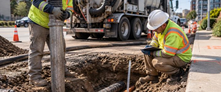
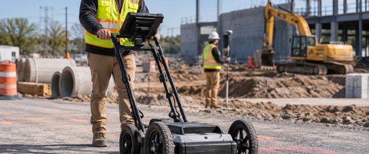
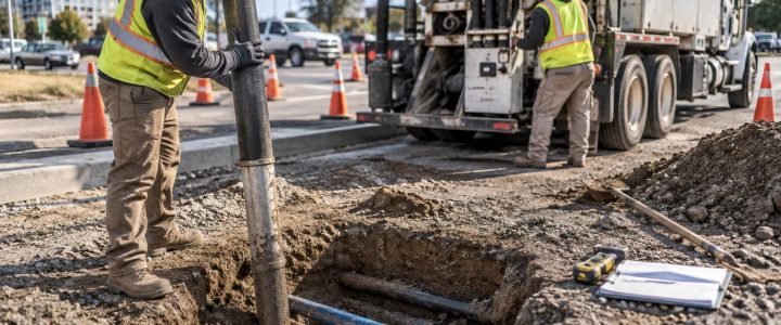
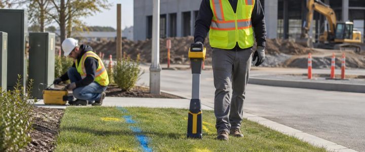
When a contractor needs to locate underground utilities before excavation, a known access point can be one of the best places to start. A valve box, meter, pedestal, pull box, cleanout, exposed conduit, or accessible tracer wire may allow a utility locator to apply a controlled signal and trace a route across the site.
This is the practical strength of electromagnetic utility locating: it can help identify and mark the likely horizontal path of a conductive utility or an installed tracer wire. It is especially useful for planning saw cuts, trench routes, foundations, directional drilling, utility repairs, and site redevelopment.
It is not an underground X-ray. An electromagnetic (EM) utility locator detects an electromagnetic field associated with a conductor. The field may come from a signal intentionally applied by the locator or from signals already present on certain energized utilities. Site conditions, congestion, grounding, access, and utility condition can all affect the result. Surface marks and receiver depth readings must be treated as field evidence to be evaluated, not as physical verification of a utility’s exact location.
What electromagnetic pipe locating can trace
EM pipe locating works best when there is a continuous conductive path that can carry a detectable signal. That path may be the utility itself or a component installed with it.
Commonly traceable facilities
- Steel, cast iron, ductile iron, and other metallic pipe
- Copper water services and copper tubing
- Metallic electrical conduit and many metallic raceways
- Communications and power cables with accessible conductive elements
- Tracer wire installed alongside plastic gas, water, sewer, force main, or irrigation pipe
- Metal pull wire, detectable tape, or other conductive locating aids when accessible and continuous
A successful trace does not by itself confirm the utility’s service, ownership, material, operating status, or whether it is active. For example, a signal on a metal pipe near a building may indicate a water line, a gas line, an abandoned pipe, or a conductor that is coupled to another facility. Project records, visible appurtenances, 811 markings, utility operator information, and field investigation all help build a more complete interpretation.
Non-metallic utilities need a conductive target
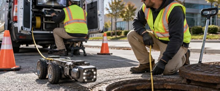
PVC, HDPE, fiberglass, concrete, clay, and other non-conductive pipe generally cannot be directly traced with standard electromagnetic locating equipment. A private utility locator may still be able to trace the route if the line has a usable tracer wire, a metallic component, detectable tape, or an inserted sonde from a pipe inspection system.
When none of those options is available, other methods may be considered based on the site and utility type. Ground penetrating radar can sometimes help identify subsurface anomalies and some buried utilities, but its results also depend on soil, depth, moisture, material contrast, congestion, and access. It should not be treated as a universal solution for non-metallic pipe.
How a locator puts a signal on a utility
For a controlled trace, the locator uses a transmitter to place a signal on the target conductor and a receiver to follow that signal at the surface. The connection method matters because it affects how well the signal stays on the intended line and how much it transfers to nearby utilities.
Direct connection
Direct connection is often the preferred method when a safe, accessible connection point is available. The transmitter lead is connected to a suitable conductive point, such as a tracer wire terminal, metal valve, exposed pipe, cable shield, or other approved access point. A ground lead is placed in the soil at an appropriate location.
This approach gives the locator the greatest control over the signal path. It can be useful for tracing a private water service from a meter, a sewer force main from a valve vault, or an electrical conduit from a cabinet. The connection must be made safely and only where conditions and site procedures allow. A locator should not assume that exposed metal is de-energized or safe to contact.
Inductive clamp
An inductive clamp can apply a signal around an accessible cable, tracer wire, or pipe without a direct metal-to-metal connection. This can be helpful where a direct connection is not practical, such as a protected cable, a wire in an enclosure, or a conductor that should not be disconnected.
The clamp still depends on a continuous conductive path. If a tracer wire is broken, poorly spliced, disconnected at a transition, or no longer electrically continuous, the trace may stop or become unreliable beyond that point.
Induction
With induction, the transmitter is placed on the ground and radiates a signal into nearby conductors. This can be useful when there is no practical access point. It is also less selective. Multiple nearby lines may pick up the signal, particularly in a utility corridor, at a building entrance, or near parallel conduits.
Induction can provide useful clues, but it requires careful interpretation and confirmation. The locator may compare responses at different frequencies, change transmitter placement, and trace suspected lines in both directions to separate a likely target from coupled utilities.
Frequency selection is a field decision, not a fixed setting
Locating frequencies are selected to match the conditions of the target and the site. In general, lower frequencies are often more selective and can reduce unwanted coupling to nearby conductors. They may not carry well on a poorly grounded, corroded, interrupted, or high-resistance route. Higher frequencies may help a signal travel farther or bridge some difficult conditions, but they can also increase signal bleed-off and induce onto adjacent utilities.
A qualified utility locator does not simply choose the strongest signal on the receiver. A strong response may be coming from a neighboring line, a bonded system, reinforced concrete, a fence, or another conductive path. Useful field checks can include:
- Comparing the response at more than one frequency
- Following the trace from the known connection point outward
- Checking signal direction and current measurements when available
- Looking for abrupt route changes or unexpected signal loss
- Reviewing whether the marked route makes sense with observed appurtenances and available records
- Investigating parallel lines individually where access permits
Why a good signal can still lead to a bad mark
The receiver responds to the electromagnetic field around a conductor, not to a visible image of the pipe or cable. The apparent center of that field can be affected by the target’s depth, orientation, neighboring conductors, grounding conditions, and signal behavior.
Parallel utilities and signal coupling
Parallel utilities are a common challenge on commercial and institutional sites. A signal placed on one line can couple onto another nearby conductor. The receiver may then detect more than one response, or the apparent route may drift from one utility to another. This is particularly common around utility banks, service entrances, industrial facilities, substations, building additions, and older utility corridors.
Bonded metallic systems can create similar complications. A line may be electrically connected to other site infrastructure through bonds, grounding, valves, metallic structures, or equipment. The signal may travel in directions that do not match the route the locator intended to trace.
Damaged or disconnected tracer wire
Tracer wire is valuable only when it remains accessible and electrically continuous enough to carry a usable signal. Breaks, poor splices, corrosion, unbonded segments, and missing termination points can limit the length of a trace. A signal that disappears may indicate a break, but it may also reflect poor grounding, a change in material, a buried splice, increased depth, or interference. It should not be interpreted as proof of a specific condition without further investigation.
Interference and difficult environments
Urban and industrial environments can be noisy. Overhead power, energized cables, cathodic protection systems, electric rail infrastructure, transformers, substations, fencing, reinforced concrete, and nearby construction activity can affect EM locating. Pavement, limited ground access, traffic control needs, and restricted access around buildings can further limit the investigation.
These conditions do not make underground utility detection impossible. They do mean the work should be planned as an investigation rather than a quick scan. The locator may need access to utility rooms, manholes, valve boxes, meters, handholes, or multiple sides of a structure to obtain and confirm meaningful traces.
How EM locators estimate depth
Many EM receivers can calculate an estimated depth after the locator has identified a usable signal and centered the apparent response. The calculation is based on characteristics of the detected field. It is not a direct measurement to the top, center, or bottom of a pipe in every situation.
Depth estimates are most useful as screening information when the signal is clean, the target is reasonably isolated, and the locator has verified the trace using appropriate field checks. The reading can become less dependable when the signal is distorted, the utility is congested, the line is not directly below the receiver, or nearby conductors are carrying the same frequency.
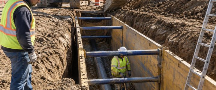
For a utility conflict at a proposed excavation, bore path, footing, or crossing, physical exposure is the appropriate way to establish the actual horizontal and vertical position. Vacuum excavation and Quality Level A test holes can expose the facility with less disturbance than conventional digging when performed with an appropriate excavation plan.
Where EM utility locating fits in construction planning
Electromagnetic locating is often a key part of Quality Level B utility designation work under ASCE 38-22, which involves designating the approximate horizontal position of subsurface utilities using surface geophysical methods. However, an EM locate alone is not automatically a complete Subsurface Utility Engineering investigation or a complete Quality Level B deliverable.
A project team may need records research, field reconnaissance, multiple geophysical methods, surveyed field markings, conflict analysis, and selective test holes depending on the scope and risk. Learn more about Subsurface Utility Engineering and Quality Level B when design decisions depend on a more structured utility investigation.
Preparing for private utility locating services
Better site information helps a utility locating company work more efficiently and interpret results more responsibly. Before the field visit, provide what is available:
- Current civil, utility, architectural, and as-built plans
- The excavation, drilling, demolition, or construction limits
- Known utility entry points, meters, vaults, valve boxes, cleanouts, and electrical rooms
- Information about planned depths, trench widths, foundation locations, and bore paths
- Site access rules, safety requirements, escorts, and traffic-control constraints
- 811 ticket status and visible public utility markings, where applicable
Private utility locating complements the 811 process. Public 811 locators generally mark facilities within the utility operators’ responsibility. Privately owned electric, water, sewer, gas, communications, site-lighting, irrigation, and other customer-side utilities may not be included. The specific responsibility boundary varies by utility and site, so the project team should confirm what has and has not been marked before work begins.
When to move from marks to test holes
Surface marks are valuable for planning, but higher-risk work requires a higher level of confirmation. Consider test holes before excavation when a marked or suspected utility conflicts with:
- A proposed utility crossing or tie-in
- Deep excavation, shoring, or a building foundation
- Directional drilling or auger work
- A utility-bank corridor or congested building entrance
- A critical facility connection, such as hospital, data, industrial-process, or fire-protection infrastructure
- A route where depth or identity is uncertain and the consequence of a strike is significant
EM utility locating can narrow the investigation, identify accessible tracing points, and help prioritize where to daylight. Test holes provide the direct observation needed to confirm the utility that is actually present at the proposed conflict location.
FAQ: electromagnetic utility locating for contractors
Can an EM locator find PVC pipe?
Not directly in most cases. A locator may trace a tracer wire, metallic tape, metallic component, or inserted sonde associated with the pipe. Without a conductive target, another investigative method may be needed.
Can EM locating tell whether a line is active or abandoned?
Not with certainty. A detectable signal can show that a conductive path is present, but it does not reliably establish service status. Records, observed connections, facility information, and physical verification may be necessary.
Is a depth reading safe to excavate on?
No. Treat it as an estimate that supports planning. Follow applicable safe-excavation practices and physically expose a utility where confirmation is required for the work.
When should a contractor hire a private utility locator?
Bring in private utility locating services before excavation, drilling, design finalization, pavement reconstruction, or demolition when private-side utilities may be present, records are incomplete, or a utility conflict could affect safety, schedule, or scope.
Plan the investigation around the work you need to perform
Electromagnetic pipe locating is most effective when the work begins with a clear question: Which utility needs to be traced, where can a signal be applied, what decision will the marks support, and where is physical verification needed? That approach turns locating from a last-minute precaution into useful information for design and construction planning.
Visionary Subsurface Solutions provides private utility locating, EM utility tracing, utility designation, and test-hole support for projects across Pennsylvania, New Jersey, Delaware, Maryland, New York, and the Washington, D.C. to New York City corridor. Contact our team to discuss the known access points, planned work limits, and level of utility investigation appropriate for your project.