Before excavation, contractors need more than a line of paint. They need to understand what that line represents, how it was produced, and where uncertainty remains. Electromagnetic (EM) utility locating is one of the most useful methods for tracing conductive underground utilities, but the quality of the result depends heavily on the signal method selected.
Active and passive EM locating are not competing services. They are different ways to detect electromagnetic fields associated with buried conductive facilities. A professional utility locator may use both methods during the same investigation, then compare the results with visible features, available records, site conditions, and other locating methods as needed.
For utility locating before excavation, active methods usually provide more control over the signal being traced. Passive methods can identify some energized or signal-carrying facilities without direct access. Neither method can confirm every buried utility, identify every line by material or ownership, or replace physical verification where the work will be close to a utility.
How electromagnetic utility locating works
An EM utility locator generally consists of a transmitter and a receiver. The transmitter applies an electrical signal to a conductive path, while the receiver detects the electromagnetic field associated with that signal at the ground surface. The operator follows the field response to estimate the horizontal route of the buried line and may use the receiver to calculate an estimated depth.
The conductive path may be a metallic pipe, cable, conduit, tracer wire, pull wire, or another connected metallic component. The equipment detects the field, not the pipe or cable itself. That distinction matters because a field can transfer, weaken, distort, or travel along an unintended path.
EM utility locating is often effective for:
- Electric, communications, and control cables that can carry a trace signal
- Metallic gas, water, fire, and process piping where an appropriate connection is available
- Metal conduit and duct banks with accessible conductive paths
- Non-metallic pipe with continuous, accessible tracer wire
- Metallic valves, risers, pedestals, cabinets, cleanouts, and other accessible utility appurtenances that help establish a trace route
Plastic, PVC, HDPE, fiberglass, concrete, and clay pipe generally cannot be directly traced with EM equipment unless there is a conductive tracer wire, metallic component, detectable tape, or another installed means of carrying a signal. A pipe may also be non-metallic while its tracer wire is detectable. In that situation, the locator is tracing the wire, not directly proving the pipe’s exact position or depth.
Passive EM locating: listening for existing signals
Passive locating uses the receiver without intentionally applying a transmitter signal. The receiver is set to detect signals that may already be present on buried conductors. Common passive modes include power-frequency and radio-frequency ranges.
When passive locating can help
Passive sweeps are useful as an early screening step and can reveal conductive utilities that have an existing detectable field. For example, an energized electrical cable may produce a power-related response. A long metallic utility may sometimes carry induced low-frequency radio energy.
Passive locating can be valuable when:
- Access to a cable, pipe, or tracer wire is not available
- A locator is checking an excavation area for additional conductive responses
- Visible utility features suggest facilities may be present but their routes are uncertain
- The field team needs to identify areas that deserve a more detailed investigation
Important limits of passive signals
A lack of passive response does not show that an area is clear. A de-energized cable, isolated metal pipe, broken tracer wire, deeply buried line, or poorly coupled facility may not produce a usable passive signal. Conversely, a passive response does not by itself establish the utility type, ownership, depth, or exact route.
Passive locating is therefore best treated as one line of evidence. It can help a locator find targets worth investigating, but it rarely offers the signal control available with an active trace.
Active EM locating: applying a controlled trace signal
In active EM utility locating, the field team uses a transmitter to place a known signal on a target conductor. The receiver is tuned to that transmitted frequency and used to trace the signal from the access point along the suspected route.
When a suitable connection and return path are available, active locating often makes it easier to distinguish the intended utility from general background signals. It also allows the operator to test multiple frequencies and observe how the signal behaves across the project area.
Direct connection
Direct connection is often the preferred active method when it can be performed safely and appropriately. One transmitter lead is connected to an accessible conductive feature, such as a tracer wire terminal, valve, meter-set piping, cable shield, or known utility conductor. The other lead is connected to a ground stake or another suitable return path.
This approach can place a relatively controlled signal on the intended line. However, direct connection is not always possible. Access may be restricted, the conductor may be inaccessible or electrically unsuitable, a tracer wire may be broken, or site conditions may prevent establishing a useful circuit. The connection point must also be selected with care; a signal applied at a building service may travel onto connected metallic systems that are not the intended target.
Induction
Induction applies a signal from the transmitter placed on the ground above a suspected utility route. No physical connection is made. This can be useful where access is unavailable or when investigating a general corridor.
The tradeoff is reduced control. The transmitted field can couple onto several nearby conductors, especially in congested areas. The resulting response may be useful for reconnaissance, but it must be interpreted carefully. An induction trace can indicate a likely conductive path; it does not automatically prove that only one utility is carrying the signal.
Clamp or coupler methods
A signal clamp, sometimes called a coupler, is placed around an accessible cable or pipe to induce a signal onto that conductor without making a direct metal-to-metal connection. This can be useful for accessible insulated cables, where a direct connection is not appropriate or practical.
Clamp methods still depend on the conductor, nearby utilities, grounding conditions, and site layout. A locator should confirm the response along the route rather than assuming the signal stayed on one line.
Choosing a locating frequency is a field decision
There is no single “best” locating frequency for every utility. Lower frequencies may be more selective and can reduce unwanted coupling to nearby lines when the target has a sound connection and a usable return path. Higher frequencies may be helpful when a weak, poorly grounded, insulated, or difficult-to-energize target needs a stronger response.
Higher frequencies can also increase the chance that the signal will bleed onto adjacent utilities or follow parallel metallic paths. That can make a line appear to shift, branch, or continue farther than the intended conductor.
A professional private utility locator may begin with a lower frequency, assess signal strength and consistency, and change frequency only when the field conditions justify it. Useful checks include:
- Comparing the receiver response at more than one frequency
- Watching for abrupt changes in signal direction or strength
- Checking for a second response offset from the expected route
- Tracing from more than one accessible point where possible
- Comparing the marked route with valves, manholes, panels, meters, pedestals, and drawings
Frequency selection is not simply about getting the strongest signal. A strong response on the wrong conductor is not a reliable locate.
Why signals become distorted in congested utility corridors
Commercial sites, campuses, industrial properties, roadway corridors, and building entrances often contain several closely spaced metallic utilities. Parallel lines can receive a transferred signal from the intended target. This is commonly called coupling. A signal can also bleed off through bonds, shared grounding, connected piping, cable shields, metallic conduit, or other conductive paths.
Field symptoms may include a response that is unusually broad, inconsistent depth estimates, a route that seems to jump sideways, or multiple peaks near each other. These conditions do not mean locating is impossible. They mean the result requires more deliberate interpretation and, often, additional verification.
Challenges increase around substations, electrical rooms, transformers, rail-adjacent infrastructure, large metal structures, reinforced concrete, fencing, cathodically protected systems, and areas with heavy electrical noise. Roadway traffic and surface metal can also complicate field work. A clear paint mark should not be mistaken for proof that these influences are absent.
What EM depth readings can and cannot tell you
Many EM receivers calculate an estimated depth by measuring characteristics of the detected signal field. This is useful for planning, but it is not a direct measurement of the pipe or cable. The estimate is most meaningful when the signal is centered over one identifiable line and the signal path is reasonably controlled.
Depth readings may be affected by distorted fields, signal transfer to parallel utilities, an off-center receiver position, bends, tees, changes in utility orientation, nearby metal, shallow parallel conductors, soil conditions, and a signal traveling on a connected facility rather than the expected target. A tracer wire depth may also differ from the top or centerline of the pipe it accompanies.
For design or excavation decisions involving close clearance, proposed crossings, or critical utility separation, daylighting is the appropriate way to verify the actual utility location and elevation. Vacuum Excavation & QL-A can expose a targeted utility with controlled excavation so the field team can document what is physically present.
Where EM locating fits in a construction utility investigation
EM locating can be an important part of a broader underground utility detection plan. Before digging, the project team should notify 811 as required for the work area and allow the public utility marking process to occur. Public 811 marks generally address participating utility facilities within the scope of that program. They may not identify privately owned lines beyond a meter, transformer, point of service, campus boundary, or other ownership transition.
Private utility locating is used to investigate those site-owned or otherwise unmarked facilities that can create conflicts for excavation, drilling, trenching, paving, foundations, utility installation, or demolition. It complements—not replaces—the 811 process.
For engineering and survey work, EM results may contribute to Quality Level B utility designation when they are developed within an appropriately planned Subsurface Utility Engineering investigation. ASCE 38-22 describes Quality Level B as designating the horizontal position of utilities through surface geophysical methods, among other information. An EM trace alone does not automatically create a complete SUE deliverable or verify vertical position. Learn more about Subsurface Utility Engineering & QL-B when utility information will influence design decisions.
When to supplement EM utility locating
EM is not the right standalone tool for every target. A practical investigation may combine methods based on the utility type, access, risk, and purpose of the work.
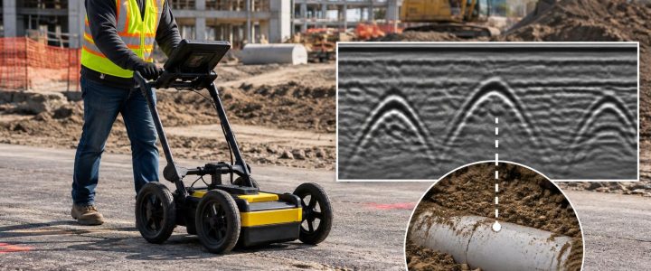
- Use GPR or other geophysical methods when non-conductive utilities are suspected, no tracer wire is available, or the team needs additional evidence beyond an EM response. Results depend on soil, moisture, depth, target size, and site conditions.
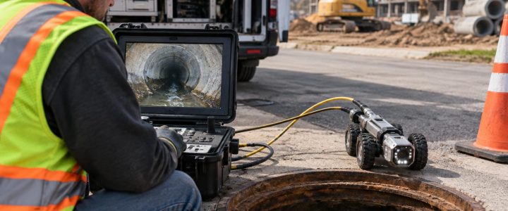
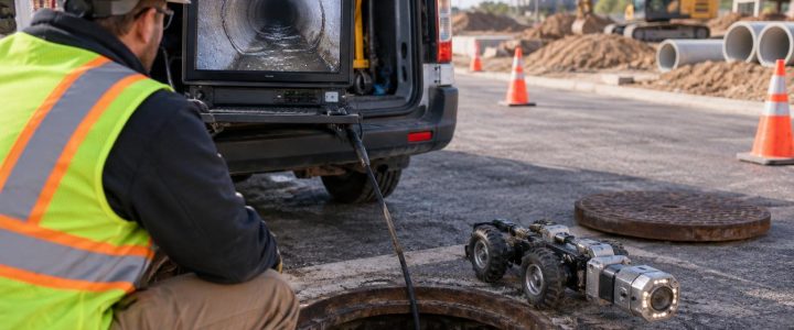
- Use CCTV or robotic pipe inspection when accessible storm or sanitary structures need internal condition or connection information. Surface locating cannot show pipe defects, blockages, or internal connections with certainty.
- Use vacuum test holes when actual horizontal position, depth, size, material, or crossing separation must be confirmed before construction proceeds.
Practical checklist before requesting utility locating services
- Define the work limits, proposed excavation depths, bore paths, foundation areas, and staging locations.
- Call 811 before excavation and preserve all existing public utility markings.
- Provide available civil plans, utility records, as-builts, survey control, and prior locate information, while recognizing that records may be incomplete.
- Identify accessible panels, meters, valves, manholes, cleanouts, pedestals, electrical rooms, and known tracer-wire termination points.
- Clear access where practical. Remove parked equipment, stored materials, and dense vegetation from the intended survey area.
- Tell the locating company about known abandoned lines, prior utility damage, energized areas, restricted access, and planned excavation methods.
- Plan time for daylighting when the work will approach marked utilities or when a utility crossing is critical.
Frequently asked questions
Can EM locating find every underground utility?
No. EM locating is most effective on conductive utilities or non-metallic utilities with a continuous, accessible conductive tracer. Non-conductive pipe without a tracer wire may require other methods, and some utilities may remain difficult to detect because of depth, access, damage, interference, or site conditions.
Does a detected EM signal prove a line is active?
No. A detected signal indicates that a conductive path is carrying or responding to an electromagnetic field. It does not, by itself, establish whether the utility is active, abandoned, energized, pressurized, owned by a particular party, or safe to excavate around.
Should excavation begin once utilities are marked?
Marked routes help the team plan and protect the area, but they do not eliminate the need for safe excavation practices. When work approaches a marked or suspected utility, the contractor should follow the applicable requirements and use appropriate methods to expose and verify the facility before relying on its position or depth.
Plan the locate around the decisions the project must make
The best EM utility locating work starts with the project question: Are you clearing a trench route, designing a utility relocation, investigating a proposed bore, mapping private services, or resolving a suspected conflict? The answer determines where to investigate, which signal methods to use, what uncertainty to document, and whether test holes should follow.
Visionary Subsurface Solutions provides private utility locating and EM utility investigations for construction, engineering, and facility projects across Pennsylvania, New Jersey, Delaware, Maryland, New York, and the Washington, D.C. to New York City corridor. Contact our team to discuss the site conditions, work limits, and level of verification your project requires.