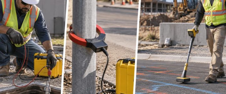
Utility investigation work often produces more than paint marks on the ground. A project team may receive utility maps, field sketches, electronic markout files, geophysical findings, quality-level designations, test-hole logs, photos, and survey data. These deliverables can be valuable for design and construction planning, but they are not all equal in purpose or reliability.
Before equipment mobilizes, contractors, engineers, and facility teams should know how to read this information. The goal is not to assume every line on a plan is exact. The goal is to identify where the remaining uncertainty could affect excavation, grading, drilling, foundations, drainage work, or utility tie-ins.
This distinction matters because utility records, visible features, instrument responses, and exposed utilities each provide a different type of evidence. A clear review process helps the team use that evidence appropriately and decide where further investigation is warranted.
Start by identifying what each deliverable is meant to show
A utility package may combine information gathered from records, field observations, geophysical methods, survey, and physical exposure. These sources should not be treated as interchangeable.
The American Society of Civil Engineers describes four quality levels for utility investigation in its ASCE 38 standard. The Federal Highway Administration also describes the same quality-level framework in its subsurface utility engineering guidance. In general, the levels move from existing records and visible features toward geophysical designation and physical exposure. ASCE 38-22 and the FHWA’s SUE guidance are useful references when a team needs to understand this framework.
Quality Level D: Existing records and recollections
Quality Level D information typically comes from available utility records, as-built drawings, old site plans, one-call responses, or staff knowledge. It can be a useful starting point, especially during early planning, but it may be incomplete or outdated.
A record may show the intended route of a utility rather than its installed location. Renovations, emergency repairs, abandoned lines, undocumented private services, and site changes can all create differences between a drawing and field conditions. Treat record-based information as a planning clue, not physical confirmation.
Quality Level C: Visible surface evidence
Quality Level C adds survey of visible above-ground features, such as manholes, valve boxes, pedestals, cleanouts, utility poles, meters, and building entry points. This can help connect records to real site features and improve map coordination.
However, a visible feature does not always reveal the full route, depth, size, condition, or connection of the line below it. For example, two nearby manholes may be part of the same system, but the actual pipe alignment and condition still need investigation.
Quality Level B: Designation by geophysical methods
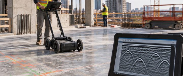
Quality Level B commonly uses field methods such as electromagnetic locating and ground penetrating radar to identify the probable horizontal position of underground utilities. Results may be marked in the field and documented on a plan.
This information is often very useful for identifying potential conflicts and planning investigation areas. Still, a designation is not the same as a direct observation. Signal strength, congestion, soil conditions, access limitations, utility configuration, and site interference can affect results. A marked route should be reviewed with its stated method, confidence, limitations, and project context in mind.
Quality Level A: Physical exposure
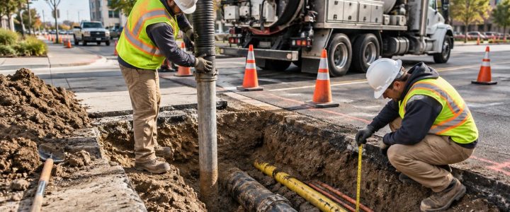
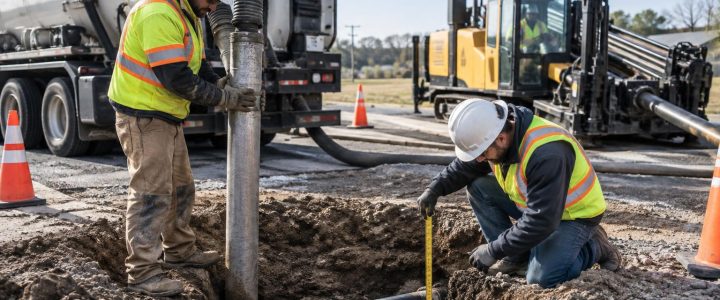
Quality Level A is based on physically exposing a utility at a specific location, often through carefully planned test holes. The observation can document the utility’s horizontal and vertical position at that point, along with other observable details such as size or material when conditions allow.
A test hole provides high-confidence information at the exposure location. It does not automatically prove that a utility maintains the same depth, alignment, or configuration farther along its route. Utilities may slope, change direction, cross other facilities, or have offsets and connections between exposure points.
Read the legend and notes before relying on the map
A utility map can look more certain than it is. Lines are clean, symbols are consistent, and colors may make separate systems easy to follow. Before using a map to make field decisions, read the legend, general notes, and any limitation statements.
Look for these details:
- Source of each utility feature: Is the line based on records, visible features, geophysical designation, physical exposure, or a combination?
- Quality-level labeling: Are utility segments or points assigned a quality level? Is the designation consistent across the map?
- Coordinate system and datum: Confirm that the map, civil plans, survey control, and machine-control files use compatible horizontal and vertical references.
- Depth notation: Determine whether a depth is measured from existing grade, a project datum, a structure rim, or another reference point.
- Survey status: Check whether marked routes and test holes were surveyed, and understand the stated accuracy or reporting method.
- Unverified or approximate areas: Do not overlook dashed lines, question marks, gaps, or notes about inaccessible areas and weak signals.
- Date of work: A map reflects conditions and observations made at a particular time. Later construction, repairs, or site work can change the field condition.
If a plan does not explain the source and limitations of the data, ask before treating it as construction-ready information. A clear deliverable should help the user distinguish observed facts from interpreted routes.
Do not confuse a utility markout with a dig clearance
Field marks communicate important information, but they do not create a blanket clearance for excavation. Their purpose is to alert the crew to a potential or designated utility route and support safer planning.
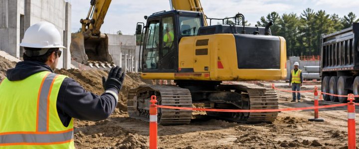
Before digging near marked utilities, the field team should review the project’s excavation approach, work limits, expected depths, and applicable owner, one-call, and site requirements. The exact process will vary by location and project. When the work could reach a known or suspected utility, project-specific verification and safe-digging procedures should be established before excavation begins.
This is especially important where marks are close together, where a proposed trench crosses multiple routes, or where a utility enters a building, vault, equipment pad, or service yard. Congested areas often deserve more attention than open areas because one mark may represent a bundle of conduits, multiple communications lines, or adjacent facilities with different owners.
Use test-hole data as decision points, not isolated facts
Test-hole reports are among the most useful construction-planning deliverables because they document what was physically observed at a particular point. A good report may include the test-hole location, date, utility description, depth information, photographs, surface elevation, utility elevation, and notes about the exposure.
When reviewing a report, focus on what the data means for the proposed work.
Compare elevations using the same reference
A common mistake is comparing one depth measured from ground surface with another elevation reported from a project datum. For example, “six feet deep” is not enough by itself to resolve a utility conflict if existing grade will be cut or filled, or if the proposed pipe profile uses benchmark elevations.
Ask whether the information is reported as:
- Depth below grade at the time of exposure
- Top-of-utility elevation
- Centerline elevation
- Bottom-of-utility elevation
- Top-of-structure or rim elevation
For gravity systems, the flow line or invert may be the critical dimension. For pressure lines, the top, centerline, or bottom of the pipe may matter depending on the proposed crossing. The design team should compare like measurements using a shared vertical datum.
Look beyond the exposed utility
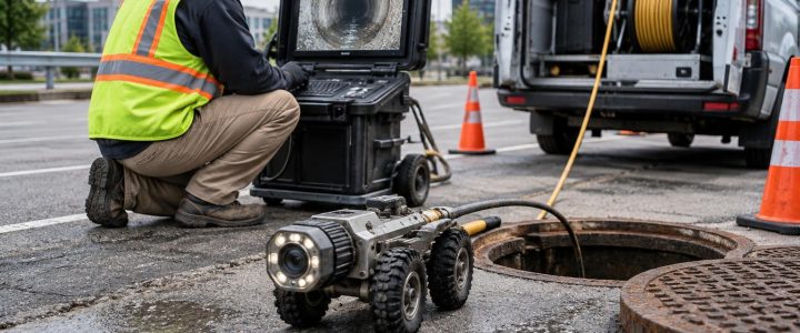
A test hole may confirm one utility while revealing other important conditions. Was there evidence of additional conduits, abandoned facilities, encasement, duct banks, concrete, unusual backfill, or tight congestion? Did the exposed line appear to cross another feature? Was the utility accessible along the planned alignment?
These observations can influence whether additional test holes, a route adjustment, revised excavation sequencing, or a different installation method should be considered.
Check the spacing against project risk
There is no universal number of test holes that fits every project. The right spacing depends on the proposed work, utility density, route geometry, changes in grade, and consequences of a conflict. A straight utility route in open ground may require a different verification approach than a crowded hospital campus, industrial facility, downtown corridor, or redevelopment site.
The important question is practical: Does the available exposure data support the decisions the team is about to make? If not, identify the uncertainty before the crew is committed to a trench, bore path, footing excavation, or structure location.
Coordinate maps with the actual construction plan
A utility investigation deliverable is most useful when it is overlaid with the work that could create a conflict. Review the utility information against proposed limits of disturbance, not just the centerline of a new pipe or roadway.
Consider the full footprint of the work:
- Trench width, shoring needs, and side slopes
- Proposed and temporary grades
- Foundation excavations, piles, and drilled shafts
- Stormwater structures and utility crossings
- Directional drilling entry and exit areas
- Crane pads, access roads, staging, and temporary fencing
- Drainage swales, landscaping, signage, and lighting bases
This review can uncover conflicts that a centerline-only check may miss. A utility outside the proposed pipe alignment may still fall within the excavation zone or be affected by grading and compaction.
For projects that need a structured approach to integrating records, field evidence, designation, and verification, Subsurface Utility Engineering & QL-B can help organize the available information for design decisions. Where direct exposure is needed to resolve a critical location or elevation question, Vacuum Excavation & QL-A provides a controlled way to obtain field observations.
Build a short preconstruction utility review
A focused meeting before excavation can prevent a utility package from being filed away and forgotten. Include the designer, superintendent, excavation lead, survey team, utility investigation provider when needed, and facility representative or owner contact when private systems are involved.
Use the meeting to answer these questions:
- Which planned activities will penetrate the ground or alter grade?
- What utility information supports each work area, and what is the source of that information?
- Which locations have direct exposure data, and which are still interpreted?
- Where are the highest-consequence conflicts or the most congested areas?
- What areas need additional designation, records review, inspection, or test holes before work begins?
- How will new findings be communicated to the field and incorporated into revised plans?
Documenting these decisions gives the field team a clearer basis for planning. It also helps prevent old maps, preliminary marks, and verified observations from being mixed together without context.
Make uncertainty visible
The best utility investigation deliverables do not imply certainty where certainty does not exist. They show what was found, how it was found, where data is limited, and what should be verified before high-risk work proceeds.
That transparency supports better decisions by designers and field crews. It can help teams prioritize investigation effort where it matters most, rather than treating every part of a site the same way.
Visionary Subsurface Solutions supports projects throughout Pennsylvania, New Jersey, Delaware, Maryland, New York, and the Washington, D.C. to New York City corridor. If you need help interpreting utility data, filling investigation gaps, or planning verification before construction, contact Visionary Subsurface Solutions to discuss your project.