A utility can be correctly shown on a plan and still create a costly field problem. The line may be larger than expected, made from a different material, installed in a casing, or part of a multi-duct bank rather than a single conduit. Those differences can change clearance requirements, excavation methods, bore paths, support needs, relocation planning, and construction sequencing.
Utility locating is an important first step, but a locate alone does not physically confirm what is underground. When the actual size, material, configuration, depth, or elevation will affect a design or excavation decision, vacuum excavation for utilities can expose the asset so those characteristics can be observed, measured, and documented.
For engineers and contractors, the goal is not simply to dig more holes. It is to select the right utility test holes at the points where verified information will reduce meaningful design, schedule, safety, or construction risk.
Why records and locate marks may not tell the whole story
Utility records, as-built drawings, GIS mapping, and field markings are useful sources of information. They should not automatically be treated as a complete representation of current field conditions. A record may show an intended installation, an approximate route, or limited information from a prior project rather than a fully measured existing condition.
Conditions can differ from records for several reasons:
- The utility was installed on a different alignment or elevation than originally planned.
- A repair, replacement, abandonment, or extension was not fully reflected in available records.
- Road reconstruction, grading, settlement, or later utility work changed the relationship between the utility and the finished surface.
- A mapped line represents a route but does not identify a casing, parallel conduits, duct-bank dimensions, or a nearby service connection.
- Different record sets use different reference points, dates, coordinate systems, or levels of detail.
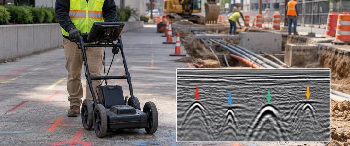
Electromagnetic (EM) locating can trace a conductive line or a trace wire, while ground penetrating radar (GPR) can identify subsurface responses that may indicate utilities or other features. Both methods support a planned investigation. However, their results are interpreted geophysical information, not direct observation of the utility. They may not reliably establish a pipe’s outside diameter, wall material, number of conduits, or exact configuration.
That distinction matters when a project team must decide whether an existing facility can remain in place, whether a proposed installation will clear it, or how a contractor should excavate around it.
What vacuum excavation can physically verify
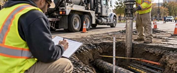
Utility potholing, also called utility daylighting or a test hole, uses controlled air or water to loosen soil while a vacuum system removes the material. Once the utility is safely exposed, qualified personnel can observe and record features that cannot be confirmed from a signal interpretation alone.
Size and outside dimensions
Physical exposure may allow the team to measure or estimate the visible outside diameter of a pipe, conduit, casing, or duct bank. This is especially important where clearance is limited. A proposed pipe may clear a six-inch line but conflict with a larger encased carrier pipe or a multi-conduit electrical bank.
The visible portion must be interpreted carefully. Insulation, coating, encasement, concrete, vault connections, and restricted exposure can affect what can be measured. The field record should state what was exposed and how the dimension was obtained rather than presenting an assumption as a precise fact.
Material and observable construction
Exposure can help identify observable characteristics such as steel, ductile iron, cast iron, copper, plastic, concrete, clay, or a combination of materials at a transition. It may also reveal protective coating, tracer wire, warning tape, casing pipe, concrete encasement, or evidence of prior repairs.
Material identification can influence construction planning. For example, a brittle legacy pipe, a pressurized line, or a duct bank with visible conduits may require a different approach than an assumed single conduit. Visual observations do not replace utility-owner confirmation, operational information, or engineering evaluation when those are required.
Configuration and number of utilities
A locate mark can represent one detectable path, but the exposed area may show a more complex condition. Vacuum excavation can help document:
- Multiple conduits within a common trench or duct bank
- Parallel pipes with limited separation
- A carrier pipe inside a casing
- Service laterals branching from a main
- Pipe crossings, transitions, fittings, or abandoned infrastructure
- Concrete encasement or other protective structures
This information is often decisive at tie-ins, roadway crossings, utility corridors, retaining-wall locations, foundation edges, and proposed directional drill alignments.
Actual horizontal position, depth, and elevation
A daylighted utility can be measured relative to the surface and nearby work. That supports utility depth verification, but the type of measurement should be stated clearly:
- Estimated depth: A depth estimate generated by EM locating or another geophysical method.
- Measured depth after exposure: A field measurement from an identified surface reference to the exposed utility.
- Surveyed elevation: A horizontal and vertical position obtained through appropriate survey procedures and tied to the project’s required control and datum.
Vacuum excavation exposes the target; it does not automatically create a surveyed elevation. When a profile design, utility crossing, or clearance requirement depends on precise coordinates, the project should arrange for appropriate survey measurement and clearly define the required point of reference, such as top of pipe, centerline, invert, top of duct bank, or top of casing.
When engineers should specify utility test holes
Not every marked utility needs to be daylighted. A practical utility verification program focuses on locations where the consequence of being wrong is high and where physical exposure can answer a specific design question.
Consider utility test hole services when any of the following conditions apply:
- A proposed storm, sanitary, water, or dry-utility installation appears to cross an existing line.
- Design profiles depend on unknown utility elevations or vertical separation.
- A line shown on records is close to a foundation, wall, pole base, structure, or deep excavation.
- A proposed HDD route must pass below or beside known utilities.
- The available records disagree with field marks, visible appurtenances, or other project information.
- A utility’s diameter, casing, or duct-bank width could affect available clearance.
- The construction team needs to confirm utility conditions before committing to a sequence, shoring approach, or equipment plan.
- A suspected abandoned line may occupy the same corridor as an active facility.
For formal Subsurface Utility Engineering work, physical exposure and precise measurement may support Quality Level A information when the investigation, measurement, documentation, and other work meet the applicable project requirements. By comparison, Quality Level B generally concerns the designation of utility routes through appropriate geophysical methods. ASCE 38-22 describes these quality levels and the processes used to communicate utility information and uncertainty. A test hole by itself does not automatically make an entire project a SUE investigation or establish Quality Level A for every utility feature.
For projects requiring coordinated SUE investigation, Visionary Subsurface Solutions can pair field verification with Subsurface Utility Engineering and QL-B services.
Plan daylighting around questions, not random locations
Effective vacuum excavation starts with a defined purpose for each hole. Before mobilization, the engineer, surveyor, utility coordinator, and contractor should identify the decisions each exposure must support.
Questions to answer before selecting locations
- Which utility creates the greatest conflict or uncertainty?
- What feature needs verification: route, top of pipe, outside diameter, invert, duct-bank edge, casing, or connection?
- What design or construction decision will use the result?
- Is one exposure sufficient, or could the utility’s route or elevation change between points?
- Does the site need survey control for a design-ready location and elevation?
- Are traffic control, pavement restoration, access limits, or environmental handling requirements likely to affect the work?
For example, an engineer evaluating a proposed gravity pipe crossing may need the existing pipe’s actual outside diameter and invert elevation, not merely an estimated depth to its top. A contractor preparing a deep excavation may instead need to daylight utilities near the proposed cut line and verify their relationship to planned support-of-excavation work. The questions are different, so the test-hole plan should be different.
Documenting observed conditions for useful field decisions
The value of utility exposure depends on what happens after the hole is opened. Field documentation should be clear enough that the design and construction teams understand what was observed, what was measured, and what remains uncertain.
A useful record may include:
- Project, test-hole identifier, date, and location description
- Utility type, if known or reasonably identified in coordination with available information
- Observed material, approximate outside dimension, and configuration
- Reference surface and measured depth information
- Surveyed coordinates and elevations when obtained
- Whether the value refers to top, centerline, invert, edge, or another defined point
- Nearby crossings, separation, casing, encasement, or parallel facilities
- Photographs showing the exposure and reference context
- Access limitations, groundwater, congestion, incomplete exposure, or other factors affecting confidence
- Backfill and surface-restoration information, as applicable
A clear limitation note is as important as a clear measurement. For instance, a hole that exposes the top and side of a utility may confirm its approximate position and apparent material but may not establish its invert elevation or full duct-bank width.
Hydro excavation or air excavation: choose for the site
Hydro excavation uses pressurized water to break up soil for removal by vacuum. It can be effective in compacted soils and conditions where water-assisted digging is appropriate. It also produces slurry that must be managed, transported, and disposed of in accordance with site-specific requirements.
Air excavation uses compressed air to loosen soil for vacuum removal. It can be advantageous where avoiding slurry is important or where dry spoils may be easier to manage. Its production can vary with soil type, moisture, compaction, and rock content.
Neither method is universally best. The appropriate approach depends on utility sensitivity, soil conditions, depth, access, groundwater, weather, restoration requirements, disposal planning, and the project’s exposure objective. Frozen ground, congested corridors, limited staging room, active traffic, and deep targets can add complexity to either method.
Vacuum excavation reduces risk, but it still requires disciplined work
Non-destructive excavation is commonly used to reduce the risk associated with mechanical digging near known or suspected underground utilities. It is not risk-free. Operators still need reliable pre-excavation information, appropriate equipment settings and techniques, controlled exposure practices, utility-owner coordination where applicable, and a safe work zone.
Mechanical excavation may still be used outside the tolerance area or after utility exposure, depending on the project plan and applicable requirements. The point of daylighting is to give the field team a verified basis for making those decisions, rather than relying entirely on assumptions.
The Federal Highway Administration recognizes the role of SUE in identifying and managing utility risks in transportation projects, while ASCE 38-22 provides a framework for communicating utility investigation quality and information. Those frameworks reinforce a practical field lesson: when the physical characteristics of a utility affect the work, direct verification can be more useful than an untested record or interpreted signal alone.
Turn utility uncertainty into a workable plan
Before finalizing a design, starting a bore, or opening a deep excavation, identify the utilities that could materially affect the work and determine which unknowns need physical confirmation. Well-planned utility daylighting can reveal whether the anticipated condition is actually present and give the team information to adjust design, sequencing, protection, or coordination before the work reaches a critical point.
Visionary Subsurface Solutions provides vacuum excavation and QL-A utility exposure services for construction, engineering, and infrastructure projects throughout Pennsylvania, New Jersey, Delaware, Maryland, New York, and the Washington, D.C. to New York City corridor. Contact our team to discuss the utility questions, site conditions, and documentation needs for your project.
Frequently asked questions
Can vacuum excavation confirm a utility’s exact depth?
It can expose the utility so depth can be physically measured from a defined surface reference. If the project needs a precise elevation tied to a project datum, survey work or other appropriate measurement procedures are also needed.
Can a test hole identify utility ownership?
No. Physical exposure may show observable characteristics, but ownership and operational status should be confirmed through utility records, owner coordination, and other appropriate project processes.
Does exposing one point verify the entire utility route?
No. A test hole confirms conditions at the exposed location. Utility alignment, depth, material, and configuration can change along the route, especially near crossings, connections, repairs, and structures.
Is utility daylighting needed after EM locating or GPR?
It may be needed when the project requires information that locating methods cannot reliably provide on their own, such as observed size, material, configuration, measured depth, or surveyed elevation at a critical point.