Congested utility corridors are one of the hardest environments for electromagnetic (EM) utility locating. A locator may detect a strong signal, yet the apparent path can drift, jump to a parallel line, or produce an unreliable depth estimate. For a contractor planning excavation, the important question is not simply, “Can we get a mark?” It is, “What does that mark represent, how confident should we be, and what must be verified before digging?”
EM utility locating remains one of the most useful tools for tracing conductive underground facilities. It can help a qualified locator identify the approximate horizontal route of metallic pipe, cable, conduit, or tracer wire. But in a corridor with several nearby utilities, electrical grounding paths, reinforced concrete, overhead power, and buried metallic debris, the signal field can become complicated quickly.
This article focuses on practical troubleshooting for utility locating for construction. The principles discussed are consistent with utility damage-prevention guidance from the Common Ground Alliance, Federal Highway Administration utility-program resources, and manufacturer training materials for electromagnetic locating equipment. Site conditions, utility configuration, and access still control what can be concluded at any individual project.
Why congested corridors create difficult EM locate conditions
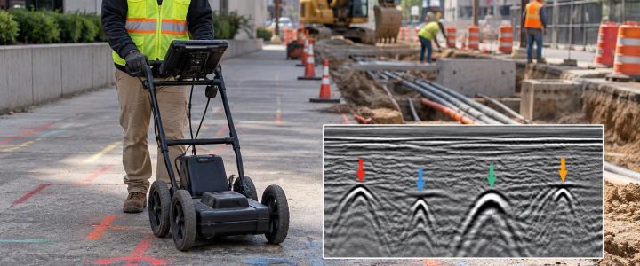
An EM utility locator does not directly “see” a pipe or cable. It detects an electromagnetic field associated with a current on a conductive target. The receiver interprets that field to help the locator trace a probable route and, under suitable conditions, estimate depth.
In an open area with a single well-isolated cable, that process can be straightforward. In a congested corridor, several conductive paths may be close enough to share, distort, or re-radiate the applied signal. The result may be a clean-looking but misleading response.
Common trouble areas include:
- Utility banks with multiple power and communications conduits
- Commercial building entries and service yards
- Industrial facilities with extensive grounding and bonding systems
- Roadway and streetscape corridors with traffic signals, street lighting, and communications
- Substations, transformers, switchgear, and electrically noisy equipment
- Areas near fencing, guardrails, reinforced concrete, rail systems, or large metallic structures
- Older sites with abandoned lines, undocumented repairs, and multiple utility generations
A mark in these conditions should be treated as a field interpretation based on detectable signals, not as proof of a utility’s exact location, material, ownership, condition, or depth.
How EM signals become distorted or misleading
Signal coupling to a parallel utility
Signal coupling occurs when the transmitted signal transfers from the intended target to a nearby conductor. A direct-connected cable can couple onto a parallel metallic pipe. A pipe may couple onto a cable, conduit, tracer wire, fence, or grounding system. Once signal is present on more than one conductor, the receiver can respond to a combined field rather than a single utility.
This is especially common where utilities run parallel for long distances. A locator may follow the intended line for part of the route, then appear to drift toward an adjacent facility as the relative signal strength changes.
Bleed-off and poor return paths
For active locating, the transmitter needs a usable path for current to travel along the target and return through the ground or another intended circuit. Poor grounding, damaged insulation, disconnected cable sections, corroded joints, insulating couplings, and open ends can weaken the signal. The applied current may bleed onto other available conductors instead.
A weak response does not prove that a line is absent or abandoned. It may mean the target cannot carry a useful locating signal over the distance being traced.
Signal distortion from nearby metal
Large nearby metallic objects can change the shape of the magnetic field the receiver is measuring. Reinforcing steel, structural steel, metal plates, parked equipment, fences, rails, and buried scrap can all affect readings. The response may become broad, asymmetric, inconsistent, or offset from the actual utility route.
Near a building, for example, a locator may be working around service conductors, grounding electrodes, structural steel, and reinforced slabs at the same time. That is a reason to slow down, collect more observations, and avoid relying on a single sweep or one frequency.
Passive energy that does not belong to one identifiable line
Passive locating can identify detectable 50/60 Hz power-related fields or radio-frequency energy already present on buried conductors. It is useful for an initial reconnaissance, but a passive response may be carried by more than one connected or coupled utility. Passive detection alone is not enough to establish a complete utility route in a complex area.
Practical signs that an EM mark needs further investigation
A skilled private utility locator evaluates signal behavior, not just the presence of a peak. The following observations can indicate that the field is distorted or that multiple conductors are involved:
- The indicated line shifts noticeably when the receiver frequency changes.
- The apparent route moves back and forth between adjacent alignments.
- The signal is very broad instead of producing a defined response.
- Depth estimates change sharply over short distances without a clear reason.
- Signal current drops rapidly or changes unexpectedly along a continuous route.
- The transmitter signal appears on several parallel features.
- Receiver orientation or a small change in position produces inconsistent results.
- The traced route conflicts with visible appurtenances, records, construction plans, or expected service entry points.
None of these signs, by itself, identifies the cause. They do indicate that the field result should be qualified and that a different locating setup, another technology, or physical verification may be needed.
How professional locators improve confidence in a congested area
Start with records, site clues, and the 811 process
Before private utility locating begins, available plans, as-builts, utility coordination records, previous test-hole information, and visible features should be reviewed. Manholes, vaults, meters, transformers, pedestals, valves, building penetrations, and utility warning signs can help establish likely routes and target access points.
Public 811 notifications remain an important first step before excavation. However, 811 marks generally address facilities within the participating utility owner’s responsibility. Privately owned electric, gas, water, sewer, communications, site lighting, irrigation, and building-service utilities may fall outside that scope. Private locating complements—not replaces—the 811 process.
Use the best available connection method
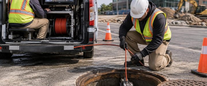
Where safe and accessible, direct connection to an identified target is usually the most controlled way to place a signal on a conductive facility. A clamp can be useful when a direct electrical connection is not appropriate or practical and the cable configuration permits it. Induction can be useful where no direct access is available, but it is more likely to energize nearby conductors in a congested area.
The method should be selected for the target, access conditions, site safety requirements, and potential for unwanted coupling. A stronger signal is not automatically a better signal. In many congested locations, the lowest practical frequency that produces a traceable response may help limit signal spread and coupling. The appropriate frequency must be confirmed in the field.
Compare multiple observations instead of trusting one reading
A professional EM utility locating workflow may include direct-connect and passive sweeps, several frequencies, receiver mode checks, signal-current observations, and tracing from more than one accessible point. The locator may compare findings with visible utility features and available records.
Agreement among independent observations can increase confidence in a proposed route. Disagreement is also useful information: it identifies uncertainty before excavation equipment reaches the area.
Mark uncertainty clearly for the construction team
Construction crews need more than paint on the ground. They need context. When marks are issued, project teams should understand the marked alignment, suspected utility type where supportable, areas of congestion, access limitations, and locations where physical exposure is recommended before intrusive work.
Marks should be protected and refreshed as needed. Earthwork, traffic, weather, paving operations, and layout changes can quickly erase or obscure utility information.
What EM locating can and cannot usually detect
EM locating is generally well suited to conductive utilities or to non-conductive utilities with a means of carrying an applied signal. Examples may include metallic pipe, metallic conduit, copper cable, steel-cased crossings, ductile iron pipe, and tracer wire installed with plastic pipe.
Plastic, PVC, HDPE, fiberglass, concrete, and similar non-conductive utilities generally cannot be directly traced with EM equipment unless they have a continuous tracer wire, metallic component, detectable tape, or an accessible sonde or transmitter placed within the line. Even then, a broken tracer wire, poor termination, multiple branches, or coupling can limit the result.
EM locating also cannot reliably determine whether a detected line is active, abandoned, empty, pressurized, safe to excavate near, or owned by a specific party. A metallic abandoned line can carry a signal. A live line may be difficult to trace. Condition and operational status require other information and, where appropriate, coordination with the responsible utility owner or facility representative.
Depth estimates: useful for planning, not a substitute for exposure
EM depth readings are calculated estimates based on the detected field and the locator’s assumptions about the target and signal. They can be useful for planning and for identifying places where a route may change elevation. They are not a measurement of exposed pipe or cable depth.
Depth estimates can be affected by lateral offset, distortion, coupled signals, parallel utilities, signal strength, soil conditions, receiver setup, target configuration, and the difference between the utility itself and an attached tracer wire or conduit. In a dense corridor, a depth number that looks precise on the receiver screen may not be precise in the ground.
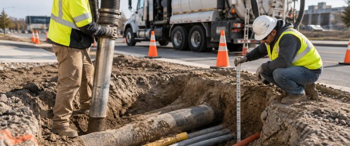
When vertical clearance, crossing order, excavation limits, drill paths, or foundation elevations matter, the utility should be physically verified with a properly planned vacuum excavation test hole. This is particularly important before drilling, pile installation, directional boring, deep excavation, or work close to high-consequence utilities.
Where EM locating fits in ASCE 38-22 utility investigation
ASCE 38-22 provides a framework for communicating the quality of subsurface utility information. Quality Level B generally involves designating the approximate horizontal position of utilities using appropriate surface geophysical methods, combined with other available information. EM utility locating can be an important tool in that work when the utility is conductive or can carry a locating signal.
An EM locate by itself does not automatically create a complete Subsurface Utility Engineering investigation or establish Quality Level B for every utility on a site. The scope, supporting records, field methods, interpretation, survey control, and documentation all matter. Quality Level A involves exposing and measuring a utility at a specific point, typically through non-destructive excavation methods.
For design-stage work, Subsurface Utility Engineering and QL-B services can organize utility information into a clearer, project-ready investigation. For conflict points where actual location and depth are critical, vacuum excavation provides the verification that surface locating cannot.
Pre-locate checklist for contractors and engineers
- Submit the 811 request early enough for required public-utility marking and site coordination.
- Define the excavation, bore, trench, foundation, or grading limits—not just the general project boundary.
- Provide current plans, known utility records, and prior test-hole data to the locating team.
- Identify available access to electrical rooms, telecom rooms, meter areas, manholes, vaults, and utility yards.
- Remove reasonable access barriers and identify locked gates, traffic-control needs, and facility safety rules.
- Tell the locator about planned depths, drilling paths, shoring, crane pads, or other high-risk activities.
- Review marks and documented limitations with the field supervisor before excavation begins.
- Plan vacuum test holes where utilities are congested, marks conflict, or vertical separation is critical.
When to bring in a private utility locating company
Private utility locating is especially valuable before work near commercial buildings, within private developments, at industrial or institutional facilities, and along site-owned utility systems. It is also appropriate when 811 marks do not cover the full work area, plans are incomplete, or an excavation crosses several suspected utilities.
Bringing a utility locating company in during planning can help crews identify likely conflicts before mobilization. Bringing one in immediately before excavation can help address changing work limits and field conditions. In either case, the best outcome comes from matching the investigation to the decision at hand: trace and designate what can be detected, document uncertainty, and daylight critical utilities before the work reaches them.
Visionary Subsurface Solutions provides private utility locating for construction and infrastructure projects throughout Pennsylvania, New Jersey, Delaware, Maryland, New York, and the Washington, D.C. to New York City corridor. Contact our team to discuss site conditions, planned work, and whether EM locating, additional investigation, or vacuum verification is appropriate for your project.