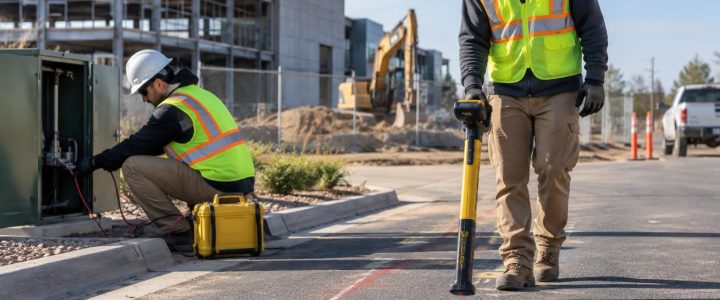
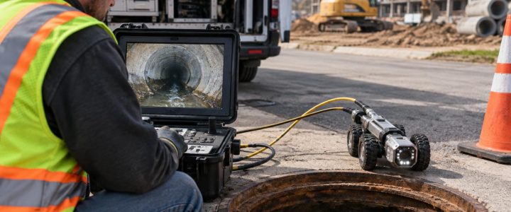
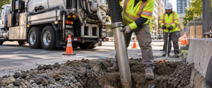
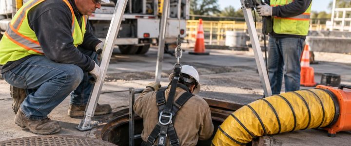
Non-metallic utility locating is a common challenge on commercial sites, campuses, industrial facilities, and redevelopment projects. Plastic water lines, HDPE gas lines, PVC irrigation systems, non-metallic conduit, concrete storm pipe, and older abandoned lines may not produce a usable electromagnetic locating signal. That can leave contractors and engineers with an important question: what is below the proposed excavation, bore path, footing, or pavement cut?
Ground penetrating radar (GPR) can be a valuable part of the answer. A GPR utility survey sends electromagnetic energy into the ground and records reflections caused by changes in subsurface materials. A buried pipe, trench backfill, void, foundation remnant, rock contact, or other feature may create a reflection that differs from the surrounding soil.
GPR can sometimes help identify likely non-metallic utilities, but it does not directly identify every pipe or provide a guaranteed depth. Results depend heavily on soil, moisture, pipe characteristics, survey access, and interpretation. For critical work, GPR findings should be considered part of a broader utility investigation and physically verified with a properly planned test hole before excavation proceeds near a suspected conflict.
Why non-metallic utilities are difficult to locate
Electromagnetic (EM) utility locating works by detecting an electromagnetic field on a conductive utility or a tracer wire. It is often highly effective for metallic pipe, energized power cable, metallic conduit, or a continuous tracer wire that can be accessed and traced.
Many private utilities do not offer that path. A PVC line has no inherent conductivity. HDPE and other plastic pipes are also non-conductive. A tracer wire may be present but broken, inaccessible, disconnected, or not installed. Concrete and clay pipe can present similar challenges unless another detectable component is available.
These conditions do not automatically mean that GPR will find the utility. Instead, they are a reason to consider GPR utility locating alongside conventional EM methods, record research, visual site review, and, where needed, vacuum excavation.
How GPR detects a possible utility
GPR does not see a labeled image of a pipe. It detects contrasts in electromagnetic properties between materials below the surface. When radar energy encounters a meaningful contrast, part of the energy may reflect back to the antenna. A trained operator reviews the timing, shape, continuity, and context of those reflections.
On a profile collected across the expected direction of a pipe, a round buried object can appear as a curved reflection commonly called a hyperbola. A utility trench may appear as a disrupted zone or a change in the surrounding material. In some cases, the backfill, bedding, or void around a pipe produces a clearer response than the pipe wall itself.
That distinction matters. A response may support an interpretation of a likely utility corridor or buried feature, but it does not prove pipe material, ownership, use, exact diameter, or service status. Similarly, an absence of a clear GPR response does not prove that no utility is present.
When GPR is useful for plastic pipe locating
GPR is often worth considering when a project involves unknown or poorly documented private utilities and EM locating alone does not provide enough confidence. Common applications include:
- Investigating a suspected PVC or HDPE water, irrigation, fire, gas, sewer, or force-main route.
- Scanning proposed excavation areas before grading, trenching, pile work, or footing installation.
- Reviewing a directional drilling path for possible crossings or undocumented obstructions.
- Locating likely utility corridors around commercial buildings, loading areas, tanks, and plant facilities.
- Investigating apparent utility crossings where record drawings are incomplete or conflicting.
- Assessing paved areas before saw cutting, pavement removal, or installation of new site utilities.
- Looking for abandoned lines, buried foundations, tanks, voids, or other subsurface anomalies that may affect construction planning.
GPR can be especially helpful when the project team needs more information than a single painted line can provide. Grid-based data collection can show the pattern and continuity of multiple anomalies across an area, which may help distinguish a potential crossing from a linear utility corridor or isolated buried object.
What affects GPR results in the field
Ground penetrating radar performance is site-specific. The same antenna and survey approach can produce useful data at one site and limited data a few blocks away. A professional GPR survey begins with an understanding of these conditions rather than an assumption that every target will be visible.
Soil type and moisture
Dry, resistive soils often allow radar energy to travel farther than wet or electrically conductive soils. Clay-rich soil, saline conditions, and high moisture can absorb or scatter radar energy, reducing penetration and making deeper features harder to interpret. Recent rain, poor drainage, and variable fill can change conditions across the same project area.
Pipe size, depth, and orientation
A larger, shallower pipe with a strong contrast against the surrounding soil may be easier to detect than a small, deep pipe. A line that crosses the survey path at a favorable angle may produce a clearer response than one that runs parallel to the scan direction. For that reason, survey lines are commonly collected in more than one direction when access and scope allow.
Surrounding materials and trench conditions
Clean granular backfill around a pipe may contrast with native soil and improve visibility. In other situations, disturbed soil, debris, multiple utility installations, or similar materials can make the pipe and its trench difficult to separate from the surrounding ground.
Surface access and site congestion
GPR antennas need practical access to the survey surface. Dense vegetation, standing water, stored materials, parked vehicles, uneven ground, metal plates, and active construction traffic can limit coverage. Near buildings and industrial equipment, surface and subsurface congestion can add interpretation challenges.
Antenna frequency
Antenna selection involves a tradeoff. Higher-frequency antennas generally provide better resolution for shallow targets but tend to have less penetration. Lower-frequency antennas may investigate deeper conditions in favorable soils but with less detail. The appropriate equipment and collection pattern should be selected for the project objective, expected target depth, and actual site conditions rather than a universal depth claim.
GPR and EM locating work better together
GPR is not a replacement for electromagnetic utility locating. The methods answer different questions and are often most useful when used together.
- EM locating can trace a conductive utility or accessible tracer wire and may provide a direct, repeatable route for that line.
- GPR can add information about non-conductive utilities, trench zones, unknown crossings, and other anomalies that do not carry a usable signal.
- Records and visual evidence may help explain field findings, identify likely service connections, and target additional investigation.
- Test holes physically expose a selected utility to confirm its location, depth, size, material, and other observable conditions.
For example, an EM locator may trace an active electric duct bank through a congested corridor. GPR may identify additional parallel anomalies or a possible perpendicular crossing. That result does not establish the identity of every anomaly. It does, however, help the project team decide where a test hole, design adjustment, or additional survey coverage is appropriate.
On projects requiring a more formal engineering utility investigation, GPR data may support elements of a broader Subsurface Utility Engineering and QL-B investigation. Collecting GPR data alone does not automatically establish a SUE Quality Level. The methods, evidence, documentation, and verification completed for the project determine how findings can be represented.
From radar response to a construction decision
It is important to separate three stages of confidence:
- Detection: The survey identifies a subsurface response or anomaly.
- Interpretation: The operator evaluates whether the response is consistent with a likely utility, trench, structure, or another feature.
- Verification: A test hole or other direct observation confirms the horizontal and vertical location of a utility and its observable characteristics.
Construction teams can use the first two stages to identify risks, plan safe investigation areas, and avoid treating unverified space as clear. But when a utility affects excavation limits, drill clearance, elevation design, or a high-consequence activity, verification should be planned before field work depends on the interpretation.
Vacuum excavation is often used for that purpose because it can expose a utility with more control than mechanical digging when performed with appropriate procedures. Visionary Subsurface Solutions provides vacuum excavation and QL-A services to help project teams verify selected findings.
How to prepare for a GPR utility survey
Better preparation helps produce a more useful GPR survey and reduces disruption to the project schedule. Before the field team arrives, provide available site information and make the intended work area accessible.
- Mark or clearly describe proposed excavation, bore, drilling, coring, or construction limits.
- Share available utility records, as-builts, prior locate marks, civil plans, and known service information.
- Identify the planned depth of work and the decisions the survey needs to support.
- Clear movable vehicles, stored materials, and debris from practical survey areas.
- Explain site access requirements, traffic controls, safety rules, and active work conditions.
- Identify areas where direct verification may be needed if a potential conflict is found.
These steps do not make a difficult site easy to scan, but they help the field team focus coverage on the locations that matter to construction.
Common misconceptions about GPR utility detection
“GPR finds every buried utility.”
No. GPR detection is limited by soil conductivity, moisture, target depth and size, surface access, clutter, and many other conditions. A utility may be present without producing an interpretable response.
“A radar response tells us exactly what the object is.”
No. GPR detects a contrast. The response may be consistent with a pipe, but it may also relate to trench backfill, debris, a foundation, a rock, or another subsurface condition. Correlation with EM results, records, and field evidence improves interpretation.
“The displayed depth is the exact utility depth.”
Not necessarily. GPR depth estimates depend on the assumed radar-wave velocity in the ground, which can vary across a site. A depth estimate is useful for planning, but physical exposure is the appropriate method for confirming critical elevations.
“Plastic pipe cannot be located.”
Plastic pipe cannot usually be directly traced with standard EM equipment unless a usable tracer wire or other conductive component is present. GPR may detect some plastic pipes or their associated trench conditions, but success is not assured. A combined investigation is often the most practical approach.
Bring in professional GPR services when uncertainty affects the work
Professional GPR utility locating services are most valuable when the consequences of an unknown condition are significant: a congested utility corridor, a planned crossing, a high-risk excavation, a drill path near facilities, or incomplete records on an older property. A qualified team can choose a suitable survey approach, integrate GPR with EM locating, identify limits in the data, and recommend verification where it matters most.
If your project in Pennsylvania, New Jersey, Delaware, Maryland, New York, or the Washington, D.C. to New York City corridor involves suspected non-metallic utilities or undocumented subsurface features, contact Visionary Subsurface Solutions to discuss the site conditions, project limits, and appropriate next steps before work begins.