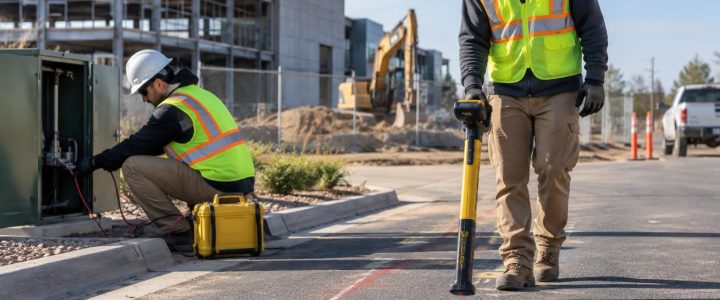
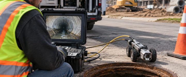
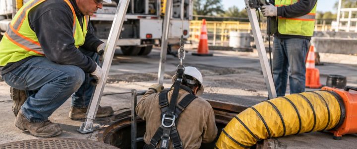
Utility test holes are most valuable when they answer a specific project question. A test hole should not be treated as a random excavation to “see what is there.” It is a planned way to physically expose a known or suspected utility and verify information that can change a design, construction approach, schedule, or budget.
For civil engineers, surveyors, SUE teams, and contractors, the goal is usually to confirm whether an existing utility conflicts with proposed work. That may mean verifying a pipe’s actual position, measuring the depth of a conduit, observing the outside diameter of a water main, documenting a duct-bank configuration, or determining the vertical separation at a crossing.
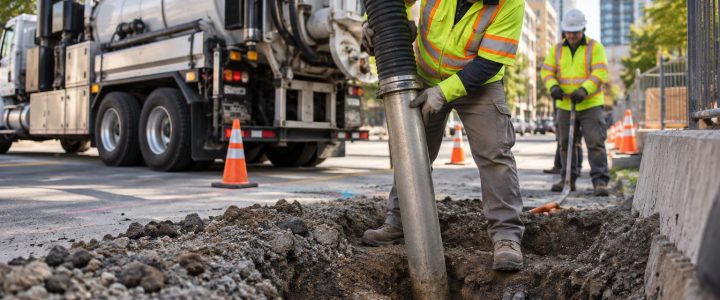
Vacuum excavation services can support that work by removing soil with air or water and a high-powered vacuum rather than relying on conventional mechanical digging directly around the utility. Once safely exposed, the utility can be observed, measured, photographed, and, when required, tied to project control by a survey professional.
Start With the Decision the Test Hole Must Support
The best utility potholing programs begin before anyone mobilizes a vacuum truck. The project team should first identify the decisions that depend on reliable subsurface information.
Common examples include:
- Can a proposed storm line pass below or above an existing utility?
- Does a planned footing, retaining wall, roadway widening, or trench conflict with a utility?
- Is there enough vertical clearance for a new utility crossing?
- Is a utility shown on record drawings actually in the expected location?
- Does an existing main have the material, diameter, or casing configuration assumed by design?
- Can an HDD bore path proceed without an unacceptable crossing risk?
- Does a contractor need to expose a utility before nearby mechanical excavation begins?
These questions help the team decide where physical verification is necessary. A utility may run through a site for hundreds of feet, but only a few locations may control the design. Focusing utility test hole services at those locations can provide useful information without unnecessary disturbance.
Locating and Physical Verification Are Different Steps
Utility locating and utility verification work together, but they do not produce the same level of information.
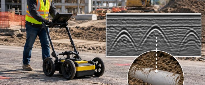
Electromagnetic locating can trace many conductive lines and provide an interpreted horizontal path. Ground penetrating radar may identify subsurface anomalies or help identify utilities in conditions where radar response is suitable. These methods are important for planning an investigation, but their results can be affected by utility material, tracer-wire condition, congestion, soil conditions, signal coupling, access, and other site factors.
An estimated depth from an electromagnetic locator is not the same as a depth measured at an exposed utility. Likewise, a radar response is not physical confirmation of a pipe’s material, outside diameter, number of conduits, or exact configuration.
Utility daylighting provides the opportunity to observe the actual exposed feature. Depending on the exposure and the project need, the field team may be able to document:
- Observed horizontal position at the test-hole location
- Depth below the existing surface or another defined reference
- Pipe or conduit outside diameter
- Observed material, such as steel, ductile iron, PVC, HDPE, concrete, or conduit types
- Number and arrangement of conduits in an exposed duct bank
- Casing, insulation, encasement, or protective features
- Utility crossings and observed vertical separation
- Visible condition concerns, where exposure permits observation
Physical exposure does not automatically create a survey-grade location or elevation. When design depends on precise coordinates, the exposed utility should be measured and tied to the project’s horizontal and vertical control using appropriate surveying procedures.
Select Test-Hole Locations That Control Risk
Test holes are commonly placed where uncertainty is highest and the consequences of being wrong are greatest. The number of holes needed varies by site, utility congestion, design stage, and the decisions at stake. A long utility route may require multiple exposures if depth, alignment, or utility conditions could change along the corridor.
Prioritize proposed crossings
A crossing is often a high-value test-hole location. Plans may show two utilities crossing, but records frequently do not establish their actual vertical separation. A vacuum excavation contractor can expose the relevant utility or utilities at the crossing area so the project team can determine whether the proposed installation has workable clearance.
Where utilities are closely spaced, it may be necessary to expose more than one feature or use multiple holes to understand the arrangement. The work should be planned carefully so one exposure does not undermine or disturb adjacent facilities.
Test design pinch points
Focus on places with limited flexibility, including:
- Low points in proposed gravity sewer or storm profiles
- New utility connections and tie-in areas
- Bridge approaches, retaining walls, and structural foundations
- Roadway drainage structures and curb-line work
- Utility corridors with limited right-of-way
- Existing vaults, manholes, handholes, and valve areas
- Transitions between private-site utilities and public utility infrastructure
These locations can determine whether a design needs to change before construction documents are issued or before crews begin excavation.
Investigate changes in utility behavior
One test hole does not prove that a utility maintains the same depth or alignment across an entire site. Additional utility daylighting may be appropriate where locator marks bend, disappear, converge with other signals, or conflict with records. Changes in grade, roadway reconstruction, previous trenching, and utility repairs can also justify more investigation.
Use a Planned Sequence for Utility Potholing
A well-run utility potholing program usually follows a sequence rather than sending crews directly to excavation.
- Review available information. Compare utility records, design drawings, 811 responses where applicable, as-builts, prior survey information, and site observations. Records are useful inputs, but they should not automatically be treated as exact field conditions.
- Perform designation where needed. Private utility locating, electromagnetic methods, and GPR can help identify likely utility paths and refine test-hole targets. Visionary Subsurface Solutions can support this early work through private utility locating when private-side infrastructure must be investigated.
- Set test-hole objectives. Identify the utility to be exposed, the information required, the anticipated work area, and the measurement or survey requirements.
- Plan access and controls. Consider traffic control, pavement conditions, property access, overhead restrictions, utility owner coordination, work hours, restoration needs, and spoil or slurry handling.
- Expose carefully. Use appropriate vacuum excavation methods and controlled digging practices around the anticipated utility location. Field personnel should stop and reassess if conditions differ from the expected utility configuration.
- Measure and document. Record the information needed for the project decision while the utility is visible. If elevations or coordinates are required, coordinate survey measurements before backfill.
- Communicate findings promptly. Designers and field crews need the results in a form they can use. A late test hole may still prevent a strike, but an early test hole can prevent an avoidable redesign or change order.
Hydro Excavation or Air Excavation?
Both methods can be used for non-destructive excavation around utilities. The right method depends on the project and site conditions rather than a single universal preference.
Hydro excavation
Hydro excavation uses pressurized water to loosen soil while a vacuum system removes the resulting slurry. It can be effective in dense or compacted soils and may support productive excavation where access and water management are practical. However, the resulting slurry requires containment, transport, and disposal consistent with project and site requirements. Water use, freezing temperatures, sensitive surfaces, and environmental constraints may also affect the plan.
Air excavation
Air excavation uses compressed air to break up soil for vacuum removal. It can reduce water use and may simplify management of dry spoils in suitable conditions. It may be useful where avoiding slurry is important. Production can vary substantially in hardpan, wet soils, clay, rocky conditions, or frozen ground. Dust control and nearby sensitive facilities also need consideration.
Neither method eliminates risk. Vacuum excavation for utilities remains active excavation work. It requires trained operators, appropriate locating and marking, controlled exposure techniques, job hazard planning, and suitable work-zone controls.
How Test Holes Relate to SUE Quality Levels
Subsurface Utility Engineering uses a structured process to manage uncertainty about existing utilities. In general terms, Quality Level B involves geophysical designation of the approximate horizontal position of utilities, while Quality Level A involves physical exposure and precise measurement/documentation at selected points.
ASCE 38-22 describes these concepts in the context of utility investigation and documentation. A vacuum excavation test hole can be an important part of obtaining Quality Level A information, but not every test hole automatically meets every project requirement for a Quality Level A deliverable. The scope, observed utility, measurement methods, survey control, records, reporting, and project standards all matter.
For design teams that need a coordinated investigation, Subsurface Utility Engineering and QL-B services can help establish the designated utility picture before the team selects the most important locations for physical verification.
The American Society of Civil Engineers and the Federal Highway Administration both describe physical exposure as a key component of the highest-confidence utility information when accurate location data is required. Their guidance also reinforces a practical point: field evidence should be documented in a way that is useful to the project, not merely collected for its own sake.
Document Information Before the Hole Is Backfilled
Once a utility is exposed, the opportunity to obtain reliable observations may be brief. A practical field record should match the project objective and commonly includes:
- Project name, test-hole identifier, date, and location description
- Utility type and observed characteristics
- Measurements to the top, centerline, or invert, clearly identifying the reference used
- Observed diameter or conduit dimensions and material
- Horizontal offsets from project control or visible reference points, as appropriate
- Surveyed coordinates and elevations when required
- Photographs showing the exposed utility and measurement setup
- Notes on nearby utilities, crossings, encasement, obstructions, and conditions affecting interpretation
- Backfill and temporary or permanent surface-restoration notes
Clear terminology matters. For example, “depth to top of pipe,” “depth to centerline,” and “invert elevation” are different measurements. A report should not leave the design team guessing which one was recorded.
Common Planning Mistakes to Avoid
Utility exposure often falls short when the investigation is treated as a last-minute field task. Avoid these common problems:
- Testing only the easiest locations: Easy access does not always mean useful information. Target design-critical points.
- Assuming one exposure represents the whole alignment: Utility depth and route can change between holes.
- Waiting until construction is underway: Earlier verification gives designers more options and reduces disruption to crews.
- Failing to arrange survey support: A visible utility does not help a profile design if required elevation data is not captured.
- Using unclear measurement references: Record whether dimensions are to top of utility, centerline, invert, or another defined point.
- Ignoring disposal and restoration planning: Hydro excavation slurry, spoils, pavement repair, landscaping, traffic, and access can affect the schedule.
Turn Exposed Utilities Into Better Project Decisions
The purpose of utility daylighting is not simply to create a hole. It is to replace a critical assumption with field-observed information. When test holes are selected around crossings, grade constraints, structures, bore paths, and other decision points, engineers can refine designs and contractors can plan excavation with a clearer understanding of the underground conditions.
For projects across Pennsylvania, New Jersey, Delaware, Maryland, New York, and the Washington, D.C. to New York City corridor, contact Visionary Subsurface Solutions to discuss a planned program of utility test holes, vacuum excavation, and physical utility verification tailored to your project.