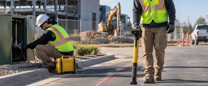
Before excavation, contractors and engineers often need more than a painted line on the ground. They need to know whether a utility is likely to conflict with a footing, bore path, trench, duct bank, drainage structure, or proposed utility crossing. Electromagnetic, or EM, utility locating can trace many conductive underground facilities and provide an estimated depth. It is an important part of private utility locating, but its depth reading should be treated as field information to evaluate—not as physical proof of a utility’s exact elevation.
A professional utility locator can use EM equipment to identify a signal on a metallic pipe, cable, conduit, or tracer wire, follow that signal across a site, and mark the interpreted path. The receiver may also calculate an estimated depth based on the signal field. That estimate is useful for planning, but several site conditions can shift the result. Where vertical position matters, vacuum excavation or a test hole is the method used to physically verify the utility.
What an EM depth reading actually measures
EM utility locating equipment does not see a pipe or cable in the same way a camera sees an object. Instead, it detects an electromagnetic field associated with a conductive facility or with a signal intentionally applied to that facility.
For active locating, a transmitter sends a signal onto a target line. A receiver detects the signal at the surface and helps the locator determine the strongest or most likely path. At an appropriate point directly over that interpreted path, the receiver can use the field’s characteristics to calculate a depth estimate.
This distinction matters: the reading is an estimate of the depth of the detected signal field, interpreted as the depth of its source. If the signal has transferred to another conductor, is traveling through a duct bank, is distorted by nearby metal, or is not centered on the intended line, the estimated depth may not represent the actual top, centerline, or bottom of the utility being investigated.
Depth to what part of the utility?
Even when the signal is clean and the utility is correctly identified, the equipment reading should be understood carefully. A utility locator commonly reports an estimated depth to the signal source or approximate centerline, depending on the equipment and mode used. That is not automatically the depth to the top of a pipe, top of a conduit bank, or top of direct-buried cable.
For construction decisions, the difference can be important. A large water main, multi-conduit electrical duct bank, or bundled communications facility has physical width and height. A centerline estimate alone may not establish safe clearance for a proposed excavation.
How a utility locator obtains a usable signal
Reliable EM utility locating starts with choosing a signal application method that fits the facility and site conditions. The goal is to put a traceable signal on the intended conductor while reducing signal transfer to adjacent utilities.
Direct connection
With direct connection, the locator connects a transmitter lead to an accessible conductive feature, such as a cable, metallic pipe, tracer wire, valve box component, pedestals, or a suitable access point. The other lead is connected to a ground point as appropriate for the equipment setup and site conditions.
Direct connection often gives the locator more control over which line carries the signal. It can be especially useful when tracing a known service from a building, meter area, utility structure, or equipment pad. It still requires interpretation because the applied signal can travel onto connected or nearby conductors.
Inductive clamp
A transmitter clamp can induce a signal onto an accessible cable or conductor without making a direct electrical connection. This is often useful where a direct connection is impractical or undesirable. The clamp must be placed around the target conductor in a way that avoids unintentionally energizing multiple conductors at once.
Induction
In induction mode, the transmitter is placed on or near the ground to broadcast a signal into the area. This method can help identify a conductive line when no accessible connection point is available. However, it provides less control. Nearby buried utilities, fences, rebar, guardrails, and other metal can receive the signal, creating multiple responses for the locator to investigate.
Induction can be productive during an initial utility investigation, but it generally calls for careful signal comparison and conservative interpretation before the results are used to make excavation decisions.
Frequency selection affects trace quality and depth confidence
EM transmitters offer different frequencies because no single frequency is best for every facility. In general, a lower frequency may help keep the signal more confined to the intended conductor when a sound connection and return path are available. A higher frequency may be helpful when the signal is difficult to establish or when tracing a small, poorly grounded, insulated, or discontinuous target.
Higher frequencies can also be more likely to couple onto nearby conductors. In a congested corridor, that can make a line appear to turn, split, or continue along an adjacent utility. The locator may compare more than one frequency and more than one connection method to determine whether the apparent route is repeatable and credible.
There is no universal “best frequency” for an underground utility locate. The proper selection depends on factors such as:
- The type and accessibility of the target utility
- Whether a direct connection, clamp, or induction method is available
- The quality of grounding and continuity along the line
- Nearby utilities, reinforcing steel, fencing, and other conductive features
- The length of the required trace
- Whether the site contains a dense duct bank or parallel utility corridor
A professional private utility locator should document uncertainty rather than force a precise-looking line where the signal behavior does not support one.
Conditions that can affect EM depth estimates
EM depth estimates can be highly useful for screening conflicts, prioritizing test holes, and planning a safe excavation approach. They become less dependable when the detected field is distorted or when the target itself is uncertain.
Parallel utilities and signal coupling
Parallel utilities are common along building fronts, roadways, service drives, and utility easements. When conductive facilities run close together, a signal applied to one can couple onto another. The receiver may respond to both fields at once, which can shift the apparent position and affect the depth estimate.
This is a particular concern around communications, electrical, gas, water, fire protection, and site lighting systems installed in the same corridor. A clean-looking surface response does not by itself prove that only one line is present.
Congested duct banks and bundled services
A duct bank may contain multiple conductors, conduits, spare ducts, grounding components, and reinforcing material. A locator may detect a strong signal associated with the bank or one part of it without resolving every individual conduit. Similarly, multiple cables in a trench can create overlapping fields.
For utility locating before excavation, the practical question is often not only “Where is the signal?” but also “What zone may contain underground infrastructure?” In a congested area, the excavation plan may need a wider tolerance area and targeted verification before mechanical digging begins.
Damaged, disconnected, or abandoned facilities
A metallic utility may not trace continuously if it has a break, insulating joint, disconnected section, poor bond, or inadequate accessible connection point. An abandoned line may still be conductive and detectable, or it may not carry a usable signal at all. EM results alone generally cannot establish whether a detected utility is active, abandoned, empty, or safe to disturb.
Project records, field evidence, utility owner information, access to structures, and physical verification may all be needed to resolve status and identity.
Nearby structures and surface metal
Buildings, substations, transformer pads, reinforced slabs, fencing, guardrails, rail systems, parked equipment, and surface metal can complicate an EM survey. Large conductive features can alter the field or carry an induced signal. The locator may need to work from multiple directions, isolate accessible conductors where possible, and compare responses across the site.
Depth, soil, and access limitations
Deep utilities may produce weaker or less distinct signals. Soil conditions can influence how a transmitter signal returns through the ground and how well a direct connection setup performs. Pavement, landscaping, traffic, restricted access, and buried obstructions can also limit where measurements can be taken. These conditions do not make locating impossible, but they affect the level of confidence that can reasonably be assigned to a marked route and estimated depth.
What EM equipment can and cannot typically locate
EM utility locating is well suited to conductive facilities and to non-metallic utilities that have a usable conductive component. Common examples include metallic pipe, metallic conduit, direct-buried metallic cable, electrical cables, communications cables with metallic elements, and tracer wires installed alongside plastic pipe.
Non-conductive materials such as PVC, HDPE, fiberglass, concrete, and clay pipe generally cannot be directly located with standard EM equipment unless there is a tracer wire, detectable tape, metallic fitting, inserted sonde, or another conductive path that can carry or emit a usable signal.
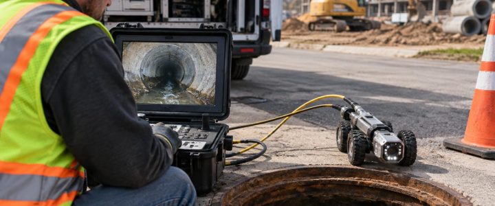
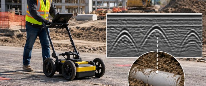
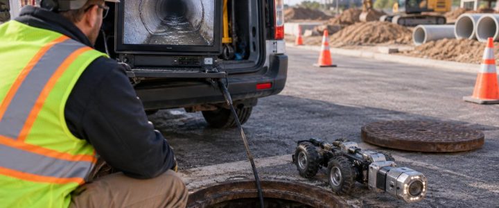
A sewer or storm line may be investigated through an access structure using a camera system with a sonde, where conditions allow. For pipe condition and route questions, video pipe inspection may provide information that a surface EM survey cannot. Ground penetrating radar may also be considered for certain non-metallic utilities or unknown subsurface features, although its results are likewise dependent on site conditions and should be interpreted with care.
EM locating, 811 marks, and private utilities
Calling 811 remains an essential step before excavation. Public utility owners or their representatives mark facilities within the scope of their notification and their responsibility. Those marks may not include privately owned lines beyond the utility’s point of service, such as privately owned electric distribution, gas, water, sewer, storm, communications, site lighting, fire protection, or process piping.
Private utility locating complements the 811 process by investigating privately owned and unknown facilities within the work area. It also helps project teams look beyond a single proposed dig location and develop a clearer picture for design, demolition, trenching, directional drilling, or site redevelopment.
For projects requiring organized utility designation and engineering deliverables, EM locating may support Quality Level B work under ASCE 38-22 when performed as part of an appropriate Subsurface Utility Engineering process. An EM locate by itself does not automatically create a complete SUE investigation or resolve every utility conflict. Learn more about Subsurface Utility Engineering and QL-B services when a project needs coordinated utility investigation for planning or design.
When estimated depth should be verified with a test hole
Mechanical excavation should not rely solely on an EM depth estimate when a utility conflict could affect safety, schedule, design, or asset protection. Vacuum excavation can expose a utility with controlled methods so the team can observe its actual horizontal position, elevation, size, material, and configuration at the test-hole location.
Consider physical verification when:
- A proposed excavation, bore, pile, footing, or structure is close to a marked utility
- Vertical separation at a crossing affects the design or construction sequence
- EM readings change significantly along the trace
- Multiple parallel utilities produce overlapping responses
- The utility is deep, critical, high consequence, or difficult to shut down
- The corridor contains private facilities not covered by available records or 811 marks
- The line appears abandoned but its status cannot be confirmed
Test holes are not a substitute for a proper utility investigation, and an EM survey is not a substitute for physical exposure. Used together, they help a project team decide where verification is necessary before the work reaches the ground.
A practical pre-excavation checklist
- Submit the required 811 notification and preserve all available public utility marks.
- Gather as-built drawings, utility plans, prior survey data, site maintenance records, and tenant information.
- Define the full work area, including staging, access routes, drill paths, dewatering, fencing, and temporary facilities.
- Identify private-side utilities, older building services, site lighting, irrigation, fire lines, and abandoned infrastructure that may not appear on records.
- Schedule private utility locating early enough to investigate ambiguous signals and plan verification.
- Review marked routes, estimated depths, limitations, and conflict areas with the excavation and design teams.
- Use vacuum excavation or other appropriate verification where the planned work approaches a suspected utility.
Plan with the signal, verify the conflict
Electromagnetic utility locating is one of the most practical tools available for tracing conductive underground utilities before construction. It can help contractors and engineers map likely routes, identify potential conflicts, and focus design or excavation efforts where they are most needed. Its value depends on thoughtful signal application, skilled interpretation, and an honest understanding of what an estimated depth does—and does not—prove.
For projects across Pennsylvania, New Jersey, Delaware, Maryland, New York, and the Washington, D.C. to New York City corridor, contact Visionary Subsurface Solutions to discuss private utility locating, EM utility investigation, and the appropriate next steps for your site.