Excavation beside a commercial building is rarely a simple “call 811 and dig” situation. Building-fed electrical lines, site lighting circuits, communications ducts, fire service piping, irrigation, and abandoned facilities may cross landscaping, parking areas, loading zones, and building additions. Many of these utilities are privately owned and may not be included in a public utility operator’s 811 response.
Electromagnetic (EM) utility locating is often the first practical method for tracing conductive underground utilities in these areas. A trained utility locator can apply or detect an electromagnetic signal, follow its path from the surface, and mark the interpreted route. The work can help contractors and engineers plan excavation, verify likely conflicts, and decide where physical exposure is needed.
However, an EM locate is an investigation, not a guarantee. The equipment detects electromagnetic fields. It does not see every buried object, confirm ownership, prove whether a line is active, or establish exact depth in all conditions. Around buildings, where signals can couple onto nearby lines and utilities may be crowded or poorly documented, a deliberate process matters.
Why commercial-building utility locating is different
Private utilities often begin where the public utility’s responsibility ends. Depending on the site and local utility practice, that transition may be near a meter, transformer, service point, property line, or another defined demarcation point. A contractor should not assume that public locate markings cover the service lateral and every downstream facility on private property.
Commercial sites also tend to have a long history. Remodels, expansions, tenant improvements, parking-lot work, and equipment replacements can leave behind old conduits, disconnected wiring, abandoned piping, and incomplete records. A line shown on a drawing may no longer be in service. A line not shown may still be present.
Common private facilities near buildings include:
- Electrical feeders from transformers, switchgear, generators, and site-lighting panels
- Communications, security, access-control, and fiber pathways in metallic conduit or with tracer wire
- Metallic water, fire protection, gas, and process piping
- Storm and sanitary systems with metallic components, tracer wire, or accessible cast-iron sections
- Grounding conductors, cathodic protection leads, and bonding systems
- Abandoned metallic conduits and pipe runs that can still carry a locating signal
How electromagnetic utility locating works
An EM utility locator generally uses a transmitter and receiver. The transmitter places a recognizable signal onto a conductive target, while the receiver detects that signal from the surface. The locator interprets the signal response to trace the probable route of the facility.
When a target can be accessed, such as a metallic pipe, cable sheath, tracer wire, valve, pedestal, handhole, or pull box, the locator may intentionally apply a signal. This is called active locating. The receiver is then used to follow the target route and place surface markings.
Passive locating is different. The receiver searches for electromagnetic fields already present on the site, such as fields associated with energized power lines or re-radiated radio-frequency energy. Passive sweeps can identify some potential utility paths, but they do not provide the same degree of target control as a well-executed active trace.
Methods used to apply an active signal
The appropriate method depends on access, safety, target type, grounding conditions, and site congestion.
- Direct connection: The transmitter is connected to an accessible conductive target. Where safely feasible, this often gives the locator the best control over the signal path.
- Inductive clamp: A clamp placed around an accessible cable or conductor applies a signal without an electrical connection. It can be useful where direct connection is unsuitable or not permitted.
- Induction: A transmitter placed on the ground induces a signal into nearby buried conductors. This can help where there is no access point, but it may energize more than one nearby line and requires careful interpretation.
Professional locators commonly compare methods and frequencies, observe the signal response, and check suspected routes from more than one direction. A strong response alone does not prove that the signal is on the intended utility. Signal coupling to a parallel facility is a frequent issue on developed sites.
What EM equipment can locate—and what it may miss
EM locating is well suited to utilities that can carry a signal. This often includes metallic pipe, metal conduit, cable shields, energized electrical cables, and non-metallic pipe with a continuous, accessible tracer wire. A detectable component must be continuous enough for the signal to travel along the route being traced.
Plastic, PVC, HDPE, fiberglass, concrete, and other non-conductive utilities generally cannot be directly traced with EM equipment. A tracer wire, metallic detectable tape, metallic component, or an inserted sonde may provide another locating path. Even then, a broken tracer wire, poor access, poor grounding, or multiple interconnected conductors can limit the result.
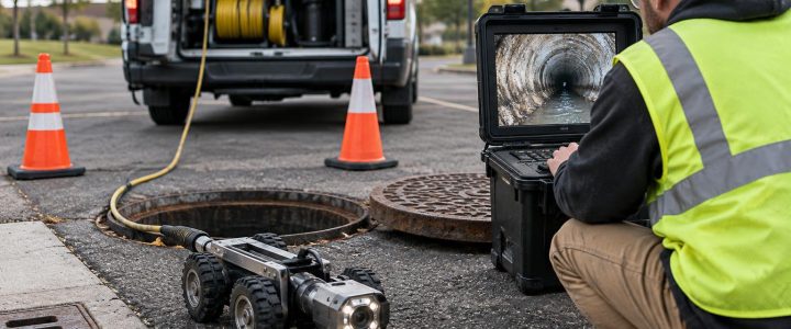
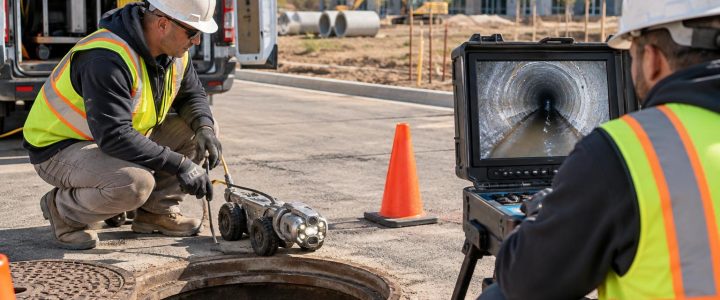
EM locating also does not establish pipe condition. If a drain line must be investigated for blockage, damage, connections, or interior defects, video pipe inspection may be the appropriate companion service.
Depth estimates: useful information, not final verification
Many receivers can calculate an estimated depth to the detected signal. That estimate can be useful for identifying potential conflicts and prioritizing test holes. It should not be treated as the actual top-of-utility depth or as clearance for mechanical excavation.
An EM depth reading is based on the geometry and strength of the electromagnetic field, not a direct measurement of the outside of a pipe or cable. The reading can be affected by:
- Signal distortion from adjacent conductors or reinforced concrete
- Signal coupling onto nearby parallel utilities
- Utility bends, branches, changes in depth, or shallow service connections
- Weak signals caused by damaged conductors, poor grounding, or signal bleed-off
- Very congested corridors, including power and communications banks
- Metal fencing, guardrails, building steel, vehicles, and nearby electrical infrastructure
- Site access limits that prevent the locator from checking the line from both sides
The Federal Highway Administration describes Quality Level B utility information as the result of surface geophysical methods used to designate the approximate horizontal position of subsurface utilities. Quality Level A uses nondestructive excavation to expose and measure the utility. That distinction is important: EM work may contribute to a broader Quality Level B investigation, but an EM trace by itself is not automatically a complete SUE deliverable or physical verification.
Why signals become difficult around buildings and industrial facilities
Building surroundings create conditions that can make utility locating more complex than an open right-of-way. Electrical rooms, transformers, generators, substations, metal-sided structures, loading docks, security systems, and dense duct banks all introduce conductive paths and electrical noise.
Parallel utilities are especially challenging. A signal intentionally placed on one line can transfer to an adjacent conductor through electromagnetic coupling, shared grounds, contact points, or common conduit systems. The receiver may then detect a convincing signal over the wrong line or over several lines. A utility locator must look for changes in signal strength, direction, current response, and depth behavior rather than simply following the strongest peak.
Abandoned facilities add another complication. A disconnected metal conduit or pipe can accept a transmitter signal even if it is no longer in service. Conversely, an active private cable may be difficult to trace if it is damaged, inaccessible, lacks a usable sheath, or is part of a complex electrical network. Field findings should be compared with visible appurtenances, available plans, utility records, and site conditions—but records should be treated as supporting information, not proof.
A practical workflow before excavation near a building
For a new utility trench, sign foundation, bollard installation, drainage repair, or directional-drilling entry pit, start the utility investigation early enough to act on the findings. The following workflow helps reduce avoidable surprises.
- Define the work area and depth. Provide limits of disturbance, proposed excavation depths, bore paths, staging areas, and known tie-in points.
- Request the public 811 locate. Follow the required notification process and respect the markings and response information received.
- Identify the private-side scope. Review likely private services from buildings, transformers, meters, site lighting, pumps, communications rooms, and detached structures.
- Gather available records. Site civil plans, electrical one-lines, as-builts, previous locate sketches, maintenance records, and tenant information can guide the field approach.
- Make the site accessible. Remove parked vehicles where possible, unlock electrical rooms or gates, identify safe access to pedestals and handholes, and communicate shutdown or access restrictions.
- Conduct a professional private utility locate. The locator can use active and passive EM methods, inspect accessible features, and document limitations or areas requiring additional investigation.
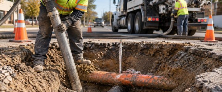
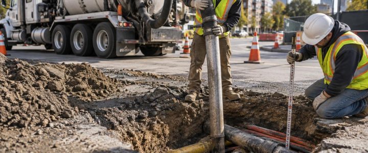
- Plan verification points. Where marked utilities conflict with excavation or the consequences of a strike are high, use vacuum excavation to expose and measure the utility before finalizing the work plan.
When to add GPR, SUE, or vacuum excavation
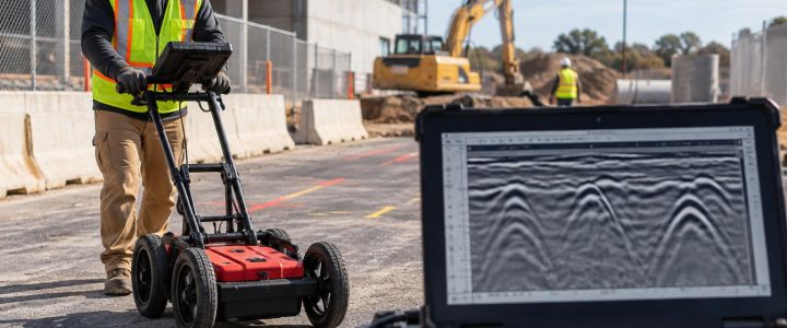
EM locating is not a replacement for every subsurface investigation method. Ground penetrating radar may help identify some non-conductive targets or unmarked anomalies where site conditions are favorable, although it also has material, moisture, depth, and congestion limitations. Camera inspection, sonde locating, and manhole investigations may be appropriate for drainage systems.
For design-stage projects with meaningful utility conflict risk, a coordinated Subsurface Utility Engineering and Quality Level B investigation can organize records research, field designation, survey, and engineering interpretation. When the exact horizontal or vertical position will affect excavation, design clearance, or construction means and methods, vacuum excavation test holes provide direct physical confirmation.
As the American Society of Civil Engineers and FHWA Quality Level framework makes clear, the level of investigation should match the consequence of being wrong. A shallow landscaping trench may call for a different level of verification than a deep utility crossing, crane foundation, retaining-wall footing, or directional-drilling route beside a building.
FAQ: EM utility locating for commercial construction
Can an EM utility locator find every underground utility?
No. EM equipment is designed to detect electromagnetic fields associated with conductive utilities or installed detectable components. Non-conductive utilities without tracer wire or another detectable feature may require other methods, and some facilities may remain undetectable from the surface.
Does an EM mark tell us the exact depth of a utility?
No. It can provide an estimated signal depth under suitable conditions. Treat that estimate as planning information. Physically expose the utility where exact depth or position is necessary for safe excavation or critical design decisions.
Can 811 marks cover a commercial property’s private utilities?
811 markings typically address facilities owned or operated by participating public utility operators, subject to the local notification system and utility policies. Private facilities beyond the operator’s responsibility often need separate investigation. Review the ticket response and markings rather than assuming the entire site is covered.
Plan the locate around the work, not just the property line
A useful EM utility locate begins with a clear construction question: What work is planned, where will it occur, how deep will it go, and what happens if a utility is not where expected? By combining public notifications, private utility locating, available records, and targeted physical verification, project teams can make better decisions before excavation begins.
Visionary Subsurface Solutions provides private utility locating and subsurface investigation services for commercial, industrial, municipal, and construction projects throughout Pennsylvania, New Jersey, Delaware, Maryland, New York, and the Washington, D.C. to New York City corridor. Contact our team to discuss the utility risks, access conditions, and verification needs for your project.
Technical references: The Federal Highway Administration’s SUE resources describe the Quality Level framework and the role of surface geophysical methods and nondestructive excavation. The American Society of Civil Engineers standards program provides information on ASCE 38-22, which establishes guidance for investigating and documenting existing subsurface utility infrastructure.