Before excavation, contractors and engineers need more than a line of paint. They need to understand what the marking represents, how the utility was traced, and where uncertainty remains. For conductive underground utilities, electromagnetic (EM) utility locating is often a central part of that investigation.
An EM utility locator does not see a pipe or cable directly. It detects an electromagnetic field associated with a conductive facility or with a signal intentionally applied to that facility. The way that signal is applied—direct connection, a signal clamp, or induction—can strongly affect the quality of the trace.
In practical terms, direct connection is usually preferred when safe access and a suitable connection point are available. A clamp is useful when a direct electrical connection is not appropriate or practical. Induction can be valuable when there is no accessible connection point, but it generally requires more careful interpretation because the signal can couple onto nearby conductors.
For utility locating before excavation, the application method should be selected based on the utility type, available access, corridor congestion, grounding conditions, and the decisions the field team needs to make. A professional private utility locator can evaluate those factors rather than relying on a single default method.
How electromagnetic utility locating works
EM utility locating equipment typically includes a transmitter and a receiver. The transmitter applies an alternating signal to a conductive path. The receiver is then used above ground to detect that signal and trace its apparent route.
The conductive path may be a metallic pipe, cable sheath, tracer wire, pull wire, conduit component, or another accessible metallic feature. The receiver helps the locator follow the signal and may provide a calculated depth estimate under suitable field conditions.
The key limitation is that the receiver follows the electromagnetic field, not a confirmed pipe wall or cable jacket. On a simple, well-isolated line, the field may produce a clear trace. In a congested corridor, the signal may travel along connected, parallel, or nearby conductors. This can make the apparent route less certain.
Direct connection: the preferred method when access allows
With direct connection, the locator connects a transmitter lead to an exposed conductive utility component. A second lead is connected to a suitable ground point. The transmitter then places a signal directly onto the target line.
Where direct connection is commonly used
- Accessible metallic gas, water, or process piping, where connection is safe and authorized
- Telecommunications pedestals, cable enclosures, terminals, and accessible metallic cable components
- Tracer wires at valve boxes, service points, handholes, or other access locations
- Accessible pull wires or metallic components within conduit systems
- Utility risers and other above-ground transition points
Why direct connection is often effective
Direct connection puts the signal onto a known access point associated with the intended facility. Compared with induction, it can provide stronger control over where the signal starts. It may also allow the locator to use a lower frequency, which can help reduce unwanted coupling to nearby utilities.
That does not make the result automatic or conclusive. Signal can still bleed onto bonded facilities, shared neutrals, parallel conductors, metallic fencing, building steel, or other connected infrastructure. A good locator checks the trace from multiple positions and watches for changes in signal response that may indicate distortion or a change in the path being followed.
Direct-connection limitations
Direct connection requires a safe, accessible, and appropriate contact point. It should not be used casually on energized electrical systems or facilities where connection could create a safety, operational, or damage risk. The party responsible for the utility may need to provide access or direction. A locator should not assume that an exposed metal component is the line that needs to be traced.
Signal clamps: applying a signal without a direct metal-to-metal connection
A signal clamp, sometimes called an induction clamp, fits around an accessible cable or pipe. The clamp induces a signal onto the conductor without the locator attaching a lead directly to bare metal.
Clamps are often useful around accessible cables in cabinets, pedestals, handholes, electrical rooms, and similar locations. They can be a practical option when direct connection is undesirable, when terminals should not be disturbed, or when a cable can be isolated enough for the clamp to target it.
What can complicate clamp locating
A clamp does not guarantee that only one buried line receives the signal. If the clamped cable is bonded, grounded, connected to other conductors, or installed alongside parallel utilities, the signal can travel beyond the expected route. Multiple conductors within the clamp opening can also make it difficult to know which path is being energized.
On complex electrical or communications systems, the locator may need to compare several transmitter settings, trace from more than one direction, and use field observations to distinguish the intended route from coupled signals. Access to as-built information, panel schedules, utility maps, and knowledgeable facility staff can be very helpful.
Induction: useful when no connection point is available
With induction, the transmitter is placed on the ground or positioned near the suspected utility route. It creates a field that can induce a signal onto nearby conductive utilities. The receiver is then used to search for and trace the induced signal.
This method can be useful when there is no accessible valve, pedestal, handhole, riser, tracer-wire termination, or other point for direct connection or clamping. It may help establish an initial route in open areas or support an investigation where access is limited.
Why induction requires extra caution in congested areas
Induction is less selective than a controlled direct connection. The transmitter may energize more than one nearby conductor, including utilities outside the intended search area. Metal fencing, guardrails, reinforced concrete, building steel, parked equipment, and surface metal can also affect the field.
For that reason, induction results should be evaluated carefully in utility-dense settings such as urban rights-of-way, industrial sites, electrical yards, building entrances, and redevelopment parcels. A trace found with induction may be a valuable lead, but it may require confirmation through a different locating setup, records review, additional technologies, or physical exposure.
Choosing the right method for the site
The best EM locating method is the one that gives the clearest defensible trace for the available conditions. The following sequence is often practical:
- Look for an accessible target. Identify valve boxes, pedestals, cleanouts, handholes, utility rooms, exposed risers, test stations, and tracer-wire terminations.
- Use direct connection where it is safe and appropriate. This often provides the greatest control over the signal path.
- Consider a clamp when a cable or conductor is accessible but should not be directly connected.
- Use induction when no practical access point exists. Treat the results with appropriate caution, especially near multiple utilities.
- Verify critical findings. Compare modes, directions, frequencies, available records, surface features, and other investigation results.
The equipment setting also matters. Lower frequencies can sometimes help keep a signal on the intended conductor, while higher frequencies can help overcome weak continuity or difficult connections. However, higher frequencies may also increase coupling onto nearby facilities. Frequency selection should follow the field response rather than a one-setting approach.
Depth estimates: useful information, not physical verification
Many EM receivers provide a calculated depth estimate. This can be useful for planning, but it is not the same as measuring an exposed utility. The estimate depends on the signal field behaving in a way the receiver can interpret.
Depth readings can be affected by signal distortion, nearby parallel utilities, utility bends, tees, changes in depth, poor grounding, multiple energized paths, overhead interference, soil conditions, and the locator’s ability to stay directly over the signal peak. A reading may represent the apparent depth of the detected field rather than the confirmed depth of the target utility.
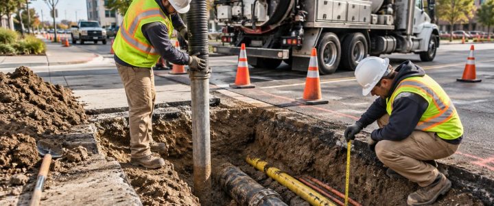
For design decisions, excavation crossings, directional drilling, deep excavation, or tight tolerance work, a calculated EM depth should be treated as preliminary. Vacuum excavation and test holes can physically expose the utility and document its actual horizontal position, elevation, size, material, and configuration at the daylighted location. Learn more about Vacuum Excavation & QL-A when field verification is needed.
What EM locating can and cannot locate
EM equipment is well suited to tracing utilities with a conductive path. Common examples include metallic pipe, metallic conduit, cable shielding, tracer wire, and detectable metallic tape when it is continuous and accessible enough to carry a signal.
Non-conductive utilities such as PVC, HDPE, fiberglass, concrete, and clay pipe generally cannot be directly traced with EM equipment alone. They may be locatable if a continuous tracer wire, metallic component, or other conductive feature is present. A sonde placed inside an accessible non-metallic pipe can sometimes be used to trace portions of that pipe, depending on access, pipe condition, and route.
EM locating also cannot reliably determine a utility’s ownership, whether it is active, its exact material, or its precise depth solely from a field signal. Those questions may require records, utility-owner input, visual inspection, CCTV inspection, test holes, or a broader subsurface investigation.
EM locating in congested utility corridors
Parallel utilities are one of the most common sources of confusion. When several conductive lines run beside one another, the signal applied to one line can couple onto another. The receiver may show a broad, shifting, or inconsistent response. A strong signal is not necessarily the correct signal.
Experienced utility locating for construction often involves checking signal direction, signal strength changes, trace consistency, and the response at known access points. The locator may change the transmitter method or frequency, work from both ends of a suspected route, and compare findings against visible features and available documentation.
Congestion should also affect the excavation plan. If markings indicate multiple utilities or if the trace is uncertain near a planned crossing, mechanical excavation should not be used to resolve the uncertainty. Plan daylighting or test holes before the work reaches the conflict area.
EM locating, private utility locating, and ASCE 38-22
Public 811 markings are an essential first step before excavation, but they commonly focus on facilities owned or operated by participating utility owners. Privately owned lines beyond the meter, service lines, campus systems, site lighting, private electric, irrigation, fire protection, and other private facilities may not be included in the public response.
Private utility locating complements the 811 process by investigating utilities within the project area that may be privately owned or otherwise outside the public locate scope. The scope should be clearly defined because no locating method can promise to identify every subsurface condition.
EM locating can be part of a Quality Level B utility designation effort under ASCE 38-22 when it is performed as part of an appropriate subsurface utility engineering process using applicable surface geophysical methods and proper documentation. An EM locate by itself does not automatically create a complete SUE deliverable or resolve all utility conflicts. For projects requiring coordinated designation, mapping, and design support, see Subsurface Utility Engineering & QL-B.
When to supplement EM locating
EM locating is one part of underground utility detection, not a substitute for every method. Consider supplemental investigation when:
- The suspected utility is non-metallic and has no usable tracer wire.
- Signals are distorted, inconsistent, or difficult to separate.
- The site contains dense parallel utilities, building steel, extensive fencing, or electrical infrastructure.
- A critical excavation, bore path, crossing, or structure foundation depends on verified utility position.
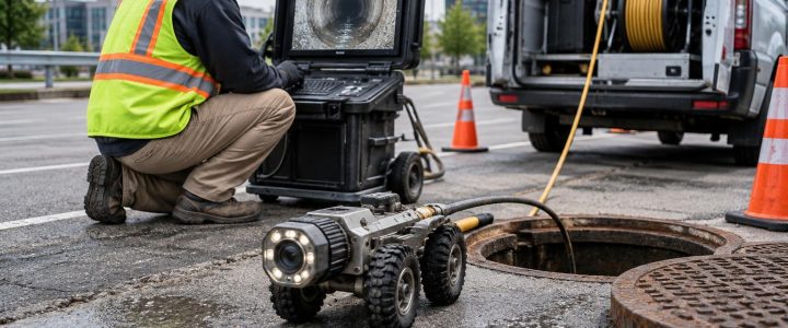
- A pipe’s interior route, condition, or connection pattern needs investigation through an accessible opening.
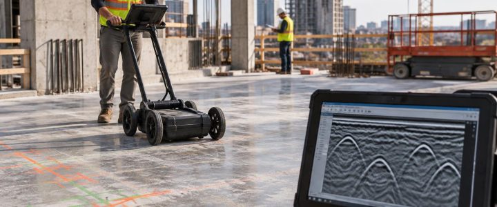
Ground penetrating radar may help identify some non-metallic utilities or subsurface anomalies where site conditions are favorable, but its performance varies with soil, moisture, depth, and congestion. CCTV inspection may help investigate accessible sewer and drainage systems. Test holes remain the appropriate method when physical confirmation of a critical utility is needed.
FAQ: EM utility locating methods
Is direct connection always more accurate than induction?
Not always, but it generally gives the locator more control over the signal path when a suitable access point is available. Field conditions, grounding, utility connections, and nearby conductors can still affect the result.
Can an EM utility locator find PVC pipe?
Not directly in most cases. The pipe may be traceable if it has a continuous tracer wire, detectable tape, metallic component, or an accessible sonde placed within the pipe.
Does an EM depth reading confirm how deep a utility is?
No. It is a calculated estimate based on the detected signal. Use physical exposure when actual depth and position are critical to design or excavation.
When should a contractor arrange a private utility locate?
Arrange it early when work will occur on private property, near buildings or facilities, in redevelopment areas, around site utilities, or anywhere 811 markings do not fully address the planned excavation area and risk.
Plan the locate around the work, not just the site boundary
Effective EM utility locating starts with a clear understanding of the proposed work: excavation limits, bore paths, proposed structures, staging areas, access routes, and areas where utilities may be crossed. Share plans, available records, site access details, and known utility features before the field visit. This helps the locating team focus on the decisions that matter most.
Visionary Subsurface Solutions provides private utility locating and subsurface investigation services throughout Pennsylvania, New Jersey, Delaware, Maryland, New York, and the Washington, D.C. to New York City corridor. Contact our team to discuss the access points, site conditions, and level of verification appropriate for your project before excavation begins.