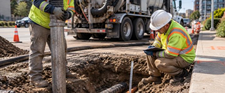
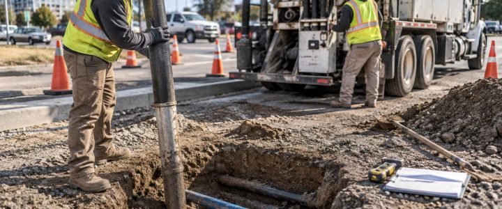
Utility daylighting answers questions that surface marks, records, and geophysical signals cannot always answer with enough confidence for design or excavation. A properly placed test hole can physically expose a pipe, conduit, duct bank, cable, or other buried feature so the team can observe its actual characteristics.
But exposure alone is not the final deliverable. The value of utility potholing depends on how well the findings are measured, recorded, and communicated to the engineer, surveyor, contractor, and utility coordinator. A hole that is backfilled without clear documentation may leave the project asking the same questions later.
This guide explains what a practical utility test hole documentation package should include, how it supports utility verification, and where additional surveying or investigation may still be needed.
Why documentation matters after utility exposure
Existing utility records are useful starting points, but they do not automatically represent current field conditions. A utility may have been installed differently than shown, relocated during past work, abandoned in place, or affected by road reconstruction, grading changes, settlement, and later utility installations. Some records show only an approximate route or do not identify every private line on a property.
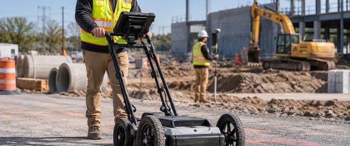
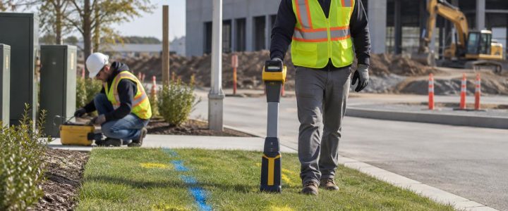
Electromagnetic locating and ground penetrating radar can help designate a utility corridor or provide an interpreted position. Those methods are important for planning, but they do not necessarily establish the utility’s actual depth, outside diameter, composition, or arrangement. Physical exposure through vacuum excavation gives the investigator an opportunity to observe and document what is actually present at a specific point.
For projects following an organized Subsurface Utility Engineering process, Quality Level B generally involves geophysical designation, while Quality Level A involves physical exposure and measurement at selected points. The ASCE 38-22 standard describes Quality Level A as the highest level of accuracy, based on exposing and measuring utilities at critical points. This does not mean every test hole automatically meets every project requirement for Quality Level A. The work scope, field methods, measurement process, and documentation must fit the investigation objective.
What a utility test hole can physically verify
When a utility is safely exposed, the field team can observe characteristics that should not be assumed from a locate mark or historical plan. Depending on the extent of exposure and the condition of the utility, a test hole may help verify:
- The utility’s horizontal position at the exposure point
- Depth below the existing surface, measured after exposure
- Top, centerline, or invert information, when the relevant feature can be identified and measured
- Outside diameter or dimensions of the exposed facility
- Observable material, such as steel, cast iron, ductile iron, PVC, HDPE, concrete, copper, or conduit
- The number and arrangement of conduits or cables within an exposed area
- Whether a line is direct-buried, encased, in a duct bank, or within a casing
- Vertical separation and apparent configuration where utilities cross
- Observable conditions such as abandoned status indicators, damaged encasement, or unanticipated obstructions
A single exposure point does not prove a utility follows the same depth, direction, or configuration across an entire site. Utilities can change grade, bend, transition materials, enter structures, or vary in depth. The design team should determine whether more test holes are needed at crossings, proposed structures, connection points, bore paths, or other high-risk locations.
Core information to record at every test hole
1. Test-hole identification and purpose
Give each test hole a unique identifier that matches the field sketch, survey file, photographs, and final report. Record the date, project name, location description, and the reason for the exposure.
For example, the purpose may be to verify a sanitary lateral before a new storm connection, establish vertical clearance at a water-main crossing, confirm duct-bank configuration near a proposed footing, or daylight a utility along a planned horizontal directional drilling route.
2. Horizontal location and reference information
Document where the exposure occurred using project control, station-and-offset information, coordinates, or a clear measured reference to fixed site features. A field sketch should show nearby curbs, structures, utility marks, proposed work, and the apparent direction of the exposed facility.
If design decisions depend on precise coordinates, coordinate the test-hole effort with a qualified surveyor. Vacuum excavation exposes the utility; it does not by itself create a surveyed location. Survey methods, control, datum, and the specific point observed must be clear in the resulting deliverable.
3. Depth, elevation, and the measurement reference
Depth and elevation are related but not interchangeable. A good record states exactly what was measured and from which reference.
- Estimated depth: A depth estimate from an electromagnetic locator or other geophysical method should be labeled as an estimate, not as a measured exposure result.
- Measured depth after exposure: Record the distance from the existing surface to the relevant utility feature, such as top of pipe, top of conduit, or centerline. Note the surface reference used.
- Surveyed elevation: When a profile, clearance calculation, or construction layout requires elevation data, a surveyor or appropriate measurement procedure should establish the elevation and identify the vertical datum.
For gravity systems, the invert may be more useful than the top of pipe. For pressurized pipe or duct banks, top-of-utility and centerline information may be the key design inputs. The documentation should identify the feature measured rather than simply reporting “depth.”
4. Utility type, size, and observable material
Record the utility type when it can be identified from markings, accessible records, visible construction, coordination with the owner, or other reliable evidence. Avoid guessing. If the service or ownership cannot be confirmed, describe what was observed instead, such as “two 4-inch orange conduits” or “unlabeled steel pipe.”
Measure and describe observable dimensions. This may include pipe outside diameter, duct-bank width and height, conduit count, casing diameter, cable bundle arrangement, or separation between parallel lines. Note whether dimensions are measured, estimated from limited exposure, or taken from records.
Material identification also deserves care. Surface color and visible texture can provide clues, but a coating, sleeve, corrosion, or restricted exposure may limit certainty. Document the observed material appearance and any markings rather than overstating the conclusion.
5. Crossings and vertical separation
Utility crossing verification is often the main reason for a test hole. At each crossing, document every exposed facility, the apparent sequence from top to bottom, and the measured vertical separation between the relevant points. Identify whether the measurement is clear separation, top-to-top distance, or centerline-to-centerline distance.
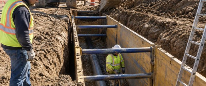
Photographs and a simple cross-section sketch are especially helpful. They allow the design team to understand whether a proposed pipe, structure, or bore path has workable clearance—or whether a redesign, protection plan, or added investigation is needed.
6. Photographs and field sketches
Take photos before excavation, during exposure, and after the utility is visible. Include a scale, ruler, measuring rod, or other reference where appropriate. Photograph utility markings, exposed materials, crossing relationships, and nearby reference points. Label images with the test-hole ID and date so they can be matched to the report.
A field sketch does not need to be complicated. It should show the hole limits, exposed utilities, orientation, measurement points, nearby features, and relevant dimensions. A clear sketch often prevents misunderstandings when the project team reviews conditions weeks later.
7. Excavation and restoration notes
Record the excavation method used, such as hydro excavation or air excavation, along with approximate hole dimensions, depth, soil conditions, groundwater, and access constraints. Note whether soil or slurry was removed, retained, or managed under the project disposal plan.
Also document backfill and surface restoration. This information helps the owner and contractor track what was disturbed and supports later coordination if the location must be revisited.
Plan test holes around decisions, not just marks
Random potholes can create activity without resolving the project’s actual risk. The best utility test-hole locations are tied to decisions that cannot be made confidently with available records and geophysical designation alone.
Common priority locations include:
- Proposed utility crossings with uncertain vertical separation
- New structures, retaining walls, foundations, and deep excavations
- Gravity-system tie-ins where invert elevation controls the design
- Congested utility corridors and duct-bank transitions
- Directional drilling entry, exit, and critical bore-path locations
- Points where records and field designation disagree
- Locations where a utility changes direction, enters a building, or approaches a vault or manhole
Early coordination between the engineer, SUE team, surveyor, and vacuum excavation contractor can define what needs to be observed at each hole. Visionary Subsurface Solutions can support this process through Subsurface Utility Engineering and QL-B services before physical exposure is selected at the most useful points.
Hydro excavation and air excavation: document the method and limitations
Hydro excavation uses pressurized water to loosen soil while a vacuum system removes the resulting slurry. It can be effective in many soil conditions and for efficient utility exposure, but water use, slurry management, site access, and freezing conditions need planning.
Air excavation uses compressed air to loosen soil for vacuum removal. It may be useful where minimizing water is important or where slurry disposal is a concern. However, production can vary with soil type, moisture, compaction, and site conditions. Neither approach is universally best.
Both methods are forms of non-destructive excavation intended to reduce the risk associated with mechanical digging around known or suspected utilities. They are not risk-free. Appropriate locating, potholing techniques, equipment settings, trained operators, work-zone controls, and jobsite safety procedures remain essential.
Common documentation mistakes to avoid
- Reporting a depth without a reference point. State whether the dimension is to top of pipe, centerline, invert, or another feature.
- Calling an estimated locate depth a verified depth. Keep geophysical estimates separate from measurements taken after exposure.
- Assuming the observed material confirms utility service or ownership. Visible characteristics alone may not establish either one.
- Failing to identify the survey datum or control. Elevation data without a known reference may not work for design.
- Taking photos with no scale or test-hole ID. Unlabeled images are difficult to use later.
- Exposing only one side of a congested crossing. The critical relationship may remain hidden unless the scope is planned around the crossing.
- Overextending conclusions. A test hole verifies conditions at that location; it does not guarantee conditions elsewhere along the alignment.
How documented test holes support better project decisions
Well-documented utility daylighting gives engineers and contractors usable information for profiles, conflict matrices, utility-relocation coordination, constructability reviews, drilling plans, and excavation sequencing. It can also help the team compare actual field conditions with plans before crews commit to excavation or installation.
For a broader understanding of utility investigation practices, the Federal Highway Administration’s utility program resources and ASCE 38-22 both emphasize systematic utility engineering and accurate information management as part of reducing utility-related project risk.
Make physical verification useful to the whole project team
Vacuum excavation for utilities is most valuable when it is planned as part of a larger investigation and followed by complete records. Before work begins, define the question each test hole must answer, the utility features to measure, the survey needs, the desired photo and sketch format, and how findings will be delivered to the design and construction teams.
Visionary Subsurface Solutions provides vacuum excavation, utility daylighting, and QL-A utility exposure services across Pennsylvania, New Jersey, Delaware, Maryland, New York, and the Washington, D.C. to New York City corridor. Contact our team to discuss a test-hole plan that helps your project verify the subsurface conditions that matter before construction moves forward.