Underground utility risk is easier to manage when the investigation starts before final design, bidding, or mobilization. Waiting until excavation is about to begin can force a team to make fast decisions with incomplete information. That often leads to field changes, redesign, schedule pressure, and a greater chance of damaging a buried line.
A utility investigation plan gives contractors, engineers, owners, and facility teams a logical way to decide what information is needed, where it is needed, and how confident the team needs to be before moving forward. It is not simply a request to “locate everything.” It is a phased process that matches the investigation effort to the project’s actual risks.
This approach is useful for site redevelopment, utility installation, roadway work, building additions, drainage improvements, campus projects, industrial facilities, and any project where buried utilities may affect the work.
Why a utility investigation plan matters
Plans, maps, and utility mark-outs are important starting points, but they are not always complete or current. A site may contain abandoned lines, private electric and communications, undocumented repairs, old service connections, drainage structures, or utilities installed after the available drawings were created.
The consequences of missing information vary by project. A shallow irrigation line may be a limited issue. An unknown electric feeder, gas line, force main, fiber route, or critical process pipe may create a serious safety, operational, or schedule concern.
A written utility investigation plan helps the project team answer practical questions early:
- Which areas will be excavated, drilled, paved, demolished, or otherwise disturbed?
- Which existing utilities may conflict with the proposed design?
- What utilities are likely public, private, or owner-maintained?
- Where are the highest-consequence crossings and congested areas?
- What level of location confidence is appropriate before design is finalized or excavation begins?
- Does the project need confirmation of pipe condition in addition to utility location?
The goal is not to promise perfect knowledge of every buried feature. The goal is to reduce avoidable uncertainty and give the team documented information for better decisions.
Start with the project limits and planned ground disturbance
A useful plan begins with a clear picture of the proposed work. Broad site boundaries alone are rarely enough. The investigation team needs to understand where the project will interact with the ground.
Provide available design backgrounds and identify the anticipated limits of:
- Trenching, utility installation, and directional drilling
- Building foundations, footings, slabs, and pile locations
- Stormwater facilities, inlets, structures, and outfalls
- Roadway reconstruction, curb work, and pavement removal
- Grading, retaining walls, landscaping, and tree planting
- Demolition, especially near existing buildings and service entrances
- Temporary works, such as construction entrances, dewatering, staging, and crane pads
It is also important to identify likely utility conflict zones. These often include utility corridors, property entrances, mechanical yards, loading areas, alleyways, transformer pads, site utility rooms, and the area between a building and the public right-of-way.
Defining these areas helps focus the effort. A project may not need the same level of investigation across an entire parcel. It may need detailed information at proposed crossings, tie-in points, deep excavations, or locations where new construction must pass through dense existing infrastructure.
Collect records, but treat them as evidence rather than final proof
Record research is often the first phase of a utility investigation plan. Useful materials can include civil plans, as-built drawings, utility connection records, prior surveys, facility maintenance files, drainage maps, GIS data, photographs, and historic site plans.
These records can reveal likely routes, structures, service laterals, pipe sizes, and past site changes. They can also help the team identify gaps. For example, a drawing may show a sanitary main leaving a building but provide no clear connection point to the public system. That uncertainty should be flagged for field investigation.
Records should be compared with site conditions, not accepted without review. Drawings may be conceptual, incomplete, based on older surveys, or affected by changes made during construction. A utility line shown in one location may be offset in the field, and an existing line may not appear on available documents at all.
Include owner knowledge in the records review
Facilities personnel, maintenance staff, and long-term site operators can provide valuable context. They may know about recurring drainage backups, abandoned tanks, past emergency repairs, equipment upgrades, or areas where crews have encountered utilities before.
This information should be documented as reported knowledge, rather than treated as verified location data. It can guide the field scope and help investigators prioritize areas that deserve closer review.
Use field locating methods that fit the suspected utility
Field investigation commonly combines several methods because no single tool responds equally well to every utility and site condition. The right method depends on the utility type, available access points, expected depth, ground conditions, congestion, and the decisions the project team needs to make.
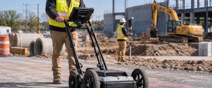
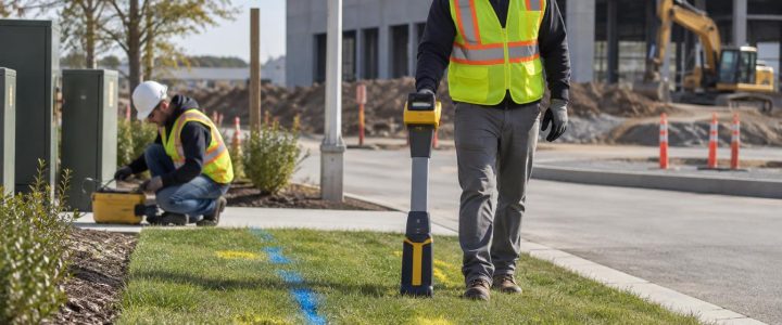
Electromagnetic locating can be effective when a conductive utility can be directly connected to, or when a usable signal can be induced onto, the line. It is commonly used for certain metallic pipes, cables, tracer wires, and accessible utility systems. Signal distortion, nearby conductors, poor grounding, congested corridors, and inaccessible connection points can affect results.
Ground penetrating radar may help identify subsurface anomalies or features, particularly where conventional signal-based locating is limited. Its performance can be affected by soil conductivity, moisture, clay content, reinforcement, depth, and site clutter. A radar response should be interpreted carefully; it may suggest a target but does not by itself establish utility ownership, material, or exact depth.
Visual inspection of accessible structures can add important information. Manholes, inlets, valve boxes, cleanouts, handholes, utility rooms, and exposed service entries may help trace a system or identify likely connections.
A good field scope also recognizes limitations. A non-conductive pipe with no tracer wire may be difficult to locate from the surface. A utility may be inaccessible, inactive, deeply buried, shielded by other utilities, or obscured by pavement and reinforcing steel. Findings should communicate both identified features and areas where uncertainty remains.
Connect field findings to a survey control system
Paint marks and field notes are useful during the investigation, but they can be lost when traffic, weather, or construction activity begins. Surveyed utility mapping creates a more durable project record and allows field findings to be compared with design information.
Where appropriate, utility indications, structures, markings, and relevant site features can be tied into project control and delivered in a format the design and construction teams can use. The level of detail should match the project need. A conceptual feasibility study may need a high-level utility constraint map, while a final design package may need more detailed plan information at conflict points.
Mapping should distinguish between observed structures, surface-located utility indications, record-based information, and physically verified locations. Combining all information into one line type without explaining its source can create a misleading level of confidence.
Use test holes to verify critical horizontal position and depth
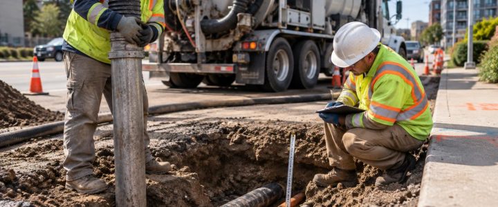
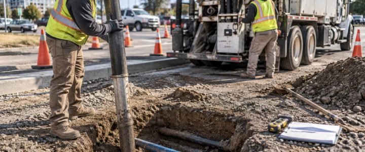
When a proposed design, excavation, or crossing depends on the actual location of a utility, vacuum excavation test holes are often the most direct way to reduce uncertainty. A test hole, also called a pothole, exposes a limited section of a buried utility so its horizontal position and depth can be measured.
Test holes are especially valuable at locations such as:
- Proposed crossings between new and existing utilities
- Deep excavation or foundation areas
- Connections to existing utility systems
- Utility corridors with limited available clearance
- Areas where surface locating results conflict with records
- Locations where a utility depth affects slope, cover, or constructability
Vacuum excavation can remove soil with controlled air or water and a vacuum system, reducing the need for mechanical digging immediately around a suspected utility. It still requires a site-specific work plan, appropriate access, and careful field practices. Exposing one point on a line does not prove that the line stays at the same depth or alignment across the entire site. Utilities can change direction, slope, or elevation between verification points.
Plan test holes around decisions, not just quantities
The best test hole program is tied to specific project decisions. Before authorizing each location, ask what the result will change. Will it confirm whether a proposed storm line can pass beneath an existing utility? Will it determine whether a footing needs to shift? Will it establish whether a utility relocation is likely?
This decision-based approach helps control scope while directing effort toward the places where better information has the greatest value.
Consider pipe condition when existing systems will remain in service
Location is only one part of the picture. When an existing sewer, storm drain, process line, or other pipe must remain in service, its condition may affect project planning as much as its route.
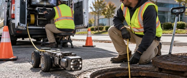
CCTV and robotic pipe inspection can help evaluate accessible pipelines for conditions such as cracking, joint separation, root intrusion, deposits, standing water, deformation, obstructions, or apparent connection issues. Inspection results can help a team decide whether a line may need cleaning, repair, replacement, bypass planning, or additional investigation.
Not every pipe can be fully inspected. Access, pipe diameter, flow conditions, debris, bends, and the condition of the line itself may limit the usable inspection distance or image quality. Still, targeted inspection is often useful before placing new pavement, building over an existing line, connecting new drainage, or relying on an aging system for increased flow.
Match the investigation to ASCE quality levels
Subsurface utility engineering, or SUE, provides a common framework for describing the reliability of utility information. Under the ASCE utility quality level concept, information generally becomes more dependable as it moves from records review toward physical verification.
- Quality Level D: Information from existing records or verbal recollection. This is useful for early awareness but has the highest uncertainty.
- Quality Level C: Visible surface features are surveyed and correlated with records. Examples include manholes, valves, utility poles, and pedestals.
- Quality Level B: Geophysical methods are used to identify the horizontal position of detectable utilities.
- Quality Level A: A utility is physically exposed, commonly through a test hole, to document its location and depth at that point.
Not every project needs Quality Level A information everywhere. A sound utility investigation plan identifies where lower-level information may be adequate and where higher-confidence verification is needed. This allows teams to use budget and schedule wisely while reducing risk at critical locations.
Turn findings into design and construction actions
The investigation is most valuable when its findings change the plan before crews are committed in the field. After the work is complete, the project team should review conflicts, gaps, and recommended next steps.
Possible actions may include adjusting a proposed alignment, changing an invert elevation, moving a structure, revising a foundation layout, planning a utility support or relocation, adding protective measures, or scheduling additional verification before a high-risk activity.
Construction documents and preconstruction meetings should also communicate the limits of the investigation. Teams need to know which utilities were verified, which were inferred from surface evidence or records, and where further field confirmation is still needed. This is more useful than presenting a map as though every depicted feature has equal certainty.
A practical sequence for utility investigations
- Define the project limits, proposed disturbance, and high-risk work areas.
- Gather available records, prior plans, and owner-maintained information.
- Review the site for visible utility features and access constraints.
- Perform targeted private utility locating and other suitable field methods.
- Survey and map relevant findings in project coordinates.
- Use CCTV or robotic inspection where pipe condition could affect the work.
- Perform vacuum excavation test holes at critical crossings, depths, and conflicts.
- Update design, estimating, sequencing, and safety planning based on the findings.
- Document remaining uncertainty and define what must be verified during construction.
Plan early enough to use the information
The strongest time to investigate is when the team still has options. Early utility information can support route selection, preliminary budgeting, and feasibility decisions. More detailed locating, mapping, inspection, and test holes can then be focused as design advances and conflict areas become clear.
For projects across Pennsylvania, New Jersey, Delaware, Maryland, New York, and the Washington, D.C. to New York City corridor, Visionary Subsurface Solutions can help develop a practical utility investigation plan using private utility locating, SUE support, utility mapping, vacuum excavation, and pipe inspection services. Contact our team to discuss the site conditions, planned work, and level of information your project may need before excavation begins.